


18
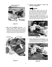
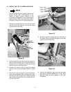
Figure 41
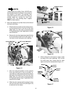
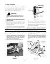
7. Compress the locking collar on the female fittings
and attach the hoses to their respective coupling
assemblies (See Figure 41). NOTE: the 45°
fittings on the hoses should angle outward and
upward to properly position the hoses.
NOTE
It may be necessary to extend or contract the lift
cylinder piston by applying pressure to the front
hitch yoke when performing the following step
8.
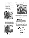
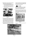
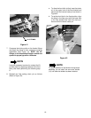
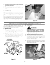
8. Reinstall the float setting clevis pin as follows
(Refer to Figure 42):
a. To allow the front hitch to float, insert the clevis
pin in the upper hole of the float bracket and
secure with the internal cotter pin as shown in
Figure 42.
b. To set the front hitch in the fixed position, align
the holes in the float arms with the lower hole
in the float bracket and insert the clevis pin.
Secure with the internal cotter pin.
Figure 42
NOTE
To ease installation of the fender/running board
assembly, do not install the new valve handle
(14) until after the fender has been installed.
COUPLING
ASSEMBLY
PROTECTIVE
CAPS
LOCKING
COLLARS
LOCKING
COLLARS
45° FITTINGS
CLEVIS PIN
FLOAT POSITION
FIXED POSITION
FLOAT ARMS
FLOAT
BRACKET