


10
NOTE
Tractors built prior to Mfg. Code 1H018G have
the standard center lift hydraulic lines routed to
the outside of the frame. The standard lines
should be moved to the inside of the frame to
provide space for routing the front hitch
hydraulic lines. The following step 5 applies
ONLY to these tractors.
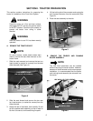
5. Move the standard lift cylinder lines to the inside of
the frame as follows:
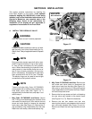
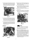
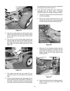
a. Remove the hex screw and valve clamp secur-
ing the hydraulic tube in the front of the valve
(See Figure 14). Use care to avoid losing the
O-Ring and backup ring (if applicable) from the
end of the tube.
b. Remove the two hex cap screws and slide the
lift valve bracket off the lift link (See Figure 14).
Use care to avoid losing the nylon bearing.
Figure 14
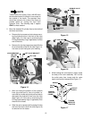
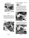
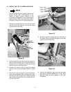
c. After first noting the position of the hydraulic
lines (top outlet port to front of cylinder) re-
move the hex screw and double valve clamp to
disconnect the hydraulic lines from the valve
(See Figure 15). Use care to avoid losing the
O-Rings and backup rings (if applicable) from
the end of the hoses.
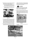
d. Slide the valve rearward off the hydraulic tube
and out of the slot in the lift link (See Figure 16)
to remove from the tractor.
Figure 15
Figure 16
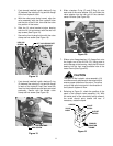
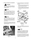
e. While holding the valve spool in place, rotate
the body of the valve assembly 180° so that
the outlet ports face inward and the valve
spool arrow points rearward(See Figure 17).
Figure 17
HEX SCREW
VALVE
CLAMP
HEX
SCREW
LIFT LINK
LIFT VALVE BRACKET
HEX CAP
SCREW
NYLON BEARING
HYDRAULIC
LINES
HEX SCREW
DOUBLE VALVE
CLAMP
LIFT LINK SLOT
HYDRAULIC
TUBE
O-RING(S)
VALVE
SPOOL
OUTLET
PORTS
VALVE
BODY
TOWARD
INSIDE OF
TRACTOR
ARROW
TOWARD
TRACTOR
FRAME