


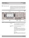
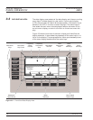
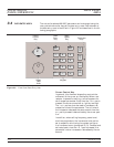

Data Entry
Area
The data entry area consists of data entry keys and
controls that provide for (1) changing values for
each 681XXC parameter, and (2) terminating the
value entry and assigning the appropriate units
(GHz, MHz, dBm, etc.).
RF Output
Control Key
The RF output control key provides for turning the
RF output power on and off. OUTPUT OFF is indi
-
cated by a red LED; OUTPUT ON by a yellow LED.
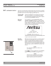
Connectors The front panel has both input and output connec
-
tors.
Modulation Connectors
The modulation connectors provide for applying ex
-
ternal AM, FM, or Square Wave modulation to the
RF output signal.
External ALC Connector
The external ALC connector provides for leveling
the RF output signal externally using either a detec-
tor or a power meter.
RF Output Connector
The RF output connector provides RF output from a
50W source.
NOTE
To prevent power losses due to an imped
-
ance mismatch, the mating connector and
cable should also be rated at 50W.
681XXC OM 3-7
LOCAL (FRONT FRONT PANEL
PANEL) OPERATION LAYOUT