


Appendix A
Rear Panel Connectors
A-1 INTRODUCTION This appendix provides descriptions for the rear panel connectors on a
typical Series 681XXC Synthesized Signal Generator.
A-2 REAR PANEL
CONNECTORS
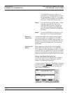
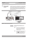
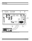
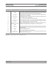
Figure A-1 provides a illustration of the rear panel and describes the
rear panel connectors.
A-3 CONNECTOR PINOUT
DIAGRAMS
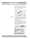
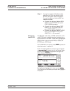
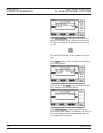
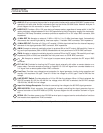
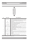
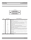
Figures A-2 and A-3 provide pinout diagrams and descriptions for the
AUX I/O and IEEE-488 GPIB multipin connectors on the rear panel.
681XXC OM A-1