


Warm Up Time:
From Standby: 30 minutes.
From Cold Start (0°C): 120 hours to achieve specified
frequency stabiltiy with aging.
Instruments disconnected from ac line power for more
than 72 hours require 30 days to return to specified fre
-
quency stability withaging.
Power:
90-132 Vac or 180-264 Vac, 48–440 Hz, 400 VA maximum
Standby: With ac line power connected, unit is placed in
standby when front panel power switch is released from the
OPERATE position.
Weight: 23 kg maximum
Dimensions:
133Hx429Wx597Dmm
RF Output Connector:
Type K female, £40 GHz models
Type V female, >40 GHz models.
ENVIRONMENTAL
Storage Temperature Range: –40°Cto+75°C.
Operating Temperature Range: 0°Cto+50°C.
Relative Humidity: 5% to 95% at 40°C.
Altitude: 4,600 meters.
EMI
Meets the radiated emission requirements of:
EN55011:1991/CISPR-11:1990 Group 1 Class A
EN50082-1:1997/
EN 61000-4-2:1995-4kVCD,8kVAD
EN 61000-4-3:1997-3V/m
ENV 50204-3V/m
EN 61000-4-4:1995 - 0.5 kV SL, 1 kV PL
EN 61000-4-5:1995-1kVL-L, 2 kV L-E
MIL-STD-461C Part 2 RE01, RE02, CE01, CE03,
CS01, CS02, CS06, RS03
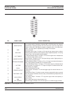
INPUTS and OUTPUTS
AM IN : Accepts an external signal to AM modulate the RF
output signal. Front or rear-panel input, 50W or 600W
impedance, both selectable from front-panel modulation
menu.
FM IN : Accepts an external signal to FM modulate the RF
output signal. Front or rear-panel input, 50W or 600W
impedance, both selectable from front-panel modulation
menu.
IN : Accepts an external TTL compatible signal to
pulse modulate the RF output signal. Front or rear-panel in
-
put, selectable from front-panel modulation menu.
EXT ALC IN (External ALC Input): Provides for leveling
the RF output signal externally with either a detector or
power meter. Signal requirements are shown in the RF Out
-
put specifications on page B-5.
RF OUTPUT: Provides for RF output from 50W source
impedance. K or V Connector, female. Option 9 moves the
RF Output connector to the rear panel.
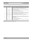
10 MHz REF IN: Accepts an external 10 MHz ±100 Hz,
0 to +10 dBm time-base signal. Automatically disconnects
the internal high-stability time-base option, if installed. 50W
impedance.
10 MHz REF OUT: Provides a 0.5 Vp-p, AC coupled,
10 MHz signal derived from the internal frequency standard.
50W impedance.
HORIZ OUT (Horizontal Sweep Output): Provides 0V at
beginning and +10V at end of sweep for all sweep modes,
regardless of sweep width. In CW mode, the voltage is pro
-
portional to frequency between 0V at low end and +10V at
the high end of range. In CW mode, if CW RAMP is en
-
abled, a repetitive, 0V to +10V ramp is provided.
B-8 681XXC OM
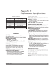
PERFORMANCE
SPECIFICATIONS
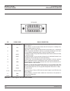
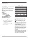
Input/Output Connectors
Nomenclature Type Location
AM IN BNC Front & Rear Panel
FM IN BNC Front & Rear Panel
IN BNC Front & Rear Panel
EXT ALC IN BNC Front & Rear Panel
RF OUTPUT
K-Connector
V-Connector
Standard-Front Panel
Option 9-Rear Panel
10 MHz REF IN BNC Rear Panel
10 MHz REF OUT BNC Rear Panel
HORIZ OUT BNC Rear Panel
AUX I/O 25-pin D-type Rear Panel
SERIAL I/O RJ45 Rear Panel
IEEE-488 GPIB Type 57 Rear Panel