


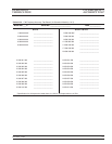
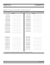
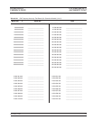
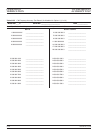
5-5 CW FREQUENCY
ACCURACY TEST
The following test verifies that the CW frequency output of the signal
generator is within accuracy specifications. Table 5-2, beginning on
page 5-7, contains test records that you can copy and use to record test
results for this test. Test records for standard 681XXC models are con
-
tained in Table 5-2A ; test records for 681XXC models with Option 11
are contained in Table 5-2B.
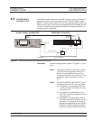
Test Setup
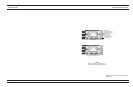
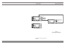
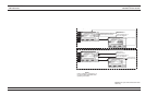
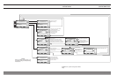
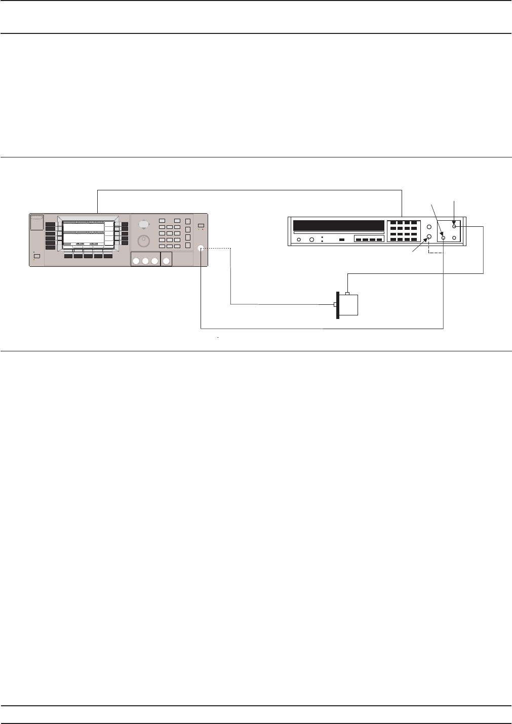
Connect the equipment, shown in Figure 5-1, as fol-
lows:
Step 1 Connect the 681XXC rear panel 10 MHz
REF OUT to the Frequency Counter 10
MHz External Reference input. If the
Frequency Counter has an INT/EXT tog
-
gle switch, ensure the switch is set to
EXT.
Step 2 Connect the 681XXC RF OUTPUT to the
Frequency Counter RF Input as follows:
a. For measuring frequencies of 0.01 to
1.0 GHz, connect to the Band 2 input
(Connection A).
b. For measuring frequencies of 1.0 to
26.5 GHz, connect to the Band 3 input
(Connection A).
c. For measuring frequencies of 26.5 to
65.0 GHz, connect to the Band 4 input
as shown in Connection B using the
appropriate waveguide mixer; Option
91 (26.5 to 40 GHz), Option 92 (40 to
60 GHz), or Option 93 (60 to 90 GHz).
681XXC OM 5-5
OPERATION CW FREQUENCY
VERIFICATION ACCURACY TEST
6 8 1 X X C S I G N A L G E N E R A T O R
F R E Q U E N C Y C O U N T E R
R F I N
B a n d 2
I n p u t
B a n d 3
I n p u t
C o n n e c t i o n A ( 0 . 0 1 t o 2 6 . 5 G H z )
C o n n e c t i o n B
( 2 6 . 5 t o 6 5 G H z )
1 0 M H z
E X T I N
B a n d 4
I n p u t
M i x e r
1 0 M H z
R E F O U T
R F O U T
Figure 5-1. Equipment Setup for CW Frequency Accuracy Test