34
SECTION IV
ELECTRICAL TROUBLESHOOTING
NOTE: Diagrams used in the section include: BB72611 and all the revisions (a revision is the letter after
the number i.e. BB72611 A, B482611.)
NOTE: A volt and ohm meter is needed for this section.
A. No Display Condition
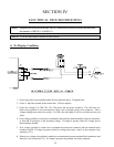
1. Check top pocket circuit breaker panel for this particular dryer. If tripped reset.
2. Check .5 amp fuse located in the control box. If blown replace.
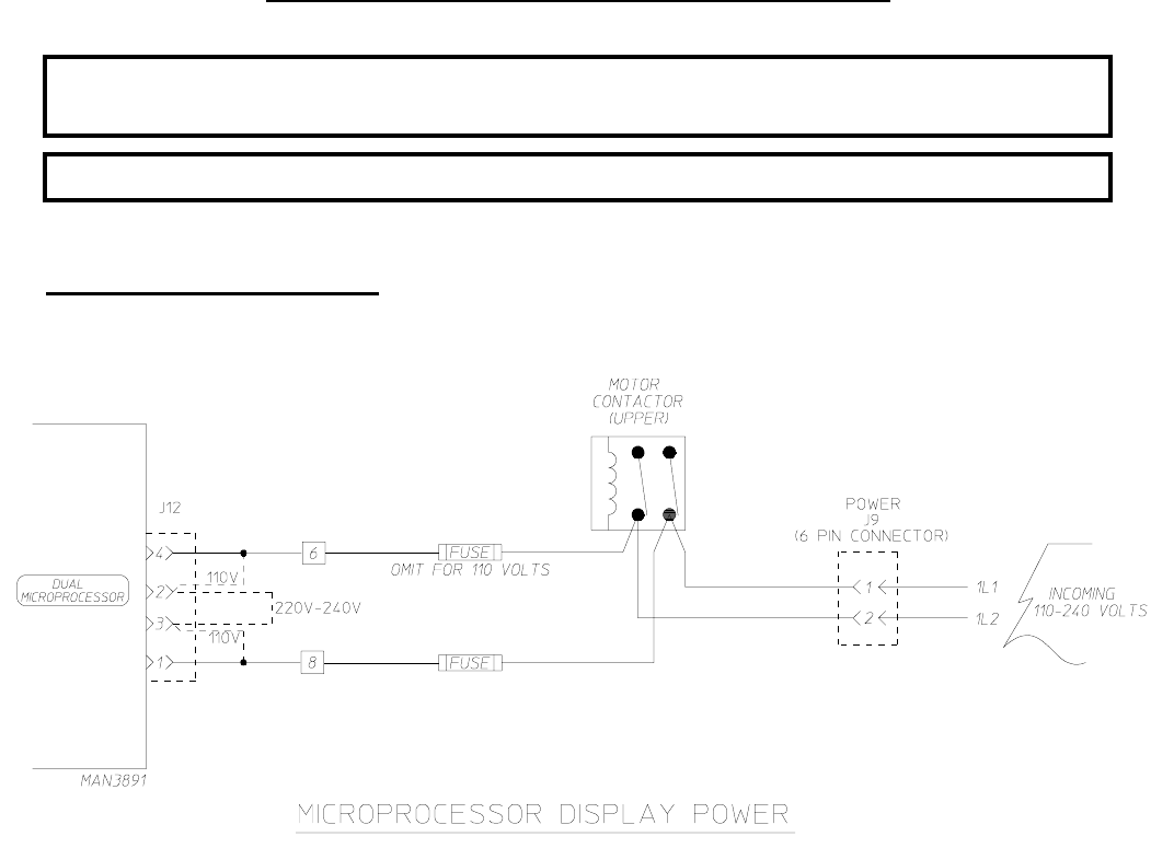
3. Check for voltage (110, 208, 220, 230, 240) across the top motor contactor. This will have two
black wires together to one point and two white wires to another point on the contactor. Take a
voltage reading across these two points. For 208 volts and higher it will be two black and two red
wires.
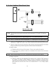
4. If no voltage, problem is a bad wire or termination between the contactor and the J9 power connector,
or from the J9 connector to the incoming voltage. If voltage is present, check for voltage across
block numbers 6 and 8.
5. If no voltage, problem is a bad wire or termination between the contactor and the terminal block
numbers 6 and 8. If voltage is present, check for voltage across pins 1 and 4 of the computer 4 pin
connector (J12).
6. If there is no voltage, the problem is a bad wire or termination between terminal block numbers 6 and
8 and the 4 pin connector (J12). If voltage is present, the problem is a faulty computer


