14
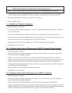
NOTE: Approximate proper belt tension - when there is a one (1) inch space between the idler adjustment
bracket and the first thread in the right hand side of the spade tension bolt.
NOTE: If lower basket (tumbler) is being serviced, the control box does not have to be removed.
3. To adjust tension, while holding spade tension bolt in place, i.e. with channel lock pliers, loosen the 9/16"
(O.D.) to adjust tension, loosen the 9/16" (O.D.) locking nut. To increase tension, loosen the inner nut.
4. Once proper adjustment is achieved, secure the 9/16" locking nut.
5. Reverse steps 1 and 2.
L. Fan Belt and Tension Adjustment
1. Discontinue power to the dryer.
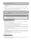
2. On the side of the fan shaft mount there is a 5/16-18 x 2" HEX head machine bolt that is used to adjust the
tension of the fan belt.
3. Loosen the two HEX head bolts on the front of the motor mount that holds it to the fan shaft mount.
4. By turning the bolt mentioned in step 2 you can now adjust the bolt tension. Tightening this bolt will increase
the tension of the fan belt and loosening the bolt will decrease the tension.
5. When proper tension is achieved retighten the two (2) HEX head bolts loosened in step 3.
6. Reestablish power to the dryer.
M. To Remove Dual Control Microprocessor (DMC) Computer Panel Assembly
1. Discontinue power to the dryer.
2. Remove the lint drawer and the control door from the dryer. Follow lint drawer, and control and lint door
removal procedures in sections A and B.
3. Remove screw in the lower right hand corner of the control panel securing the panel to the control box.
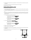
4. Open the control panel and disconnect all the harnesses that are connected to the dual microprocessor control
(DMC) computer; the two (2) 9-pin wire harness connectors and the 4-pin connector wiring harness.
5. To remove the control panel assembly from the control box, gently tap the bottom edge of the control panel
while lifting panel upwards off hinges.
6. Reverse procedure for reinstalling the control panel assembly.
7. Reestablish power to the dryer.
N. To Replace Dual Control Microprocessor (DMC) Computer
1. Discontinue power to the dryer.
2. Remove the lint drawer and the control door from the dryer. Follow lint drawer, and control and lint door
removal procedures in sections A and B.
3. Remove screw in the lower right hand corner of the control panel securing panel to control box.
4. Open control panel and disconnect all the harnesses that are connected to the dual microprocessor control
(DMC) computer; the two (2) 9-pin wire harness connectors, the 3-pin connector wiring harness coming
from the coin acceptor optic switch, and the one (1) 4-pin power wire harness connector.


