


23
1. Discontinue power to the dryer.
2. Remove the lint drawer, and the control and lint drawer. Follow lint drawer, and control and lint door removal
procedures in section A and B.
3. If the lower basket (tumbler) is being serviced, proceed to step 4. Slide the control box out three quarters of
the way and disconnect the three (3) wire harness connectors located at the back of the control box. Then
remove the control box from the dryer.
4. Remove front panel from the basket (tumbler) being serviced. Follow front panel removal procedure in
section E.
5. Remove belt from dryer. Follow removal procedure in section H.
6. Remove the upper half of the rear split back guard panel to either the top or the bottom basket (tumbler),
depending on which basket (tumbler) is being serviced.
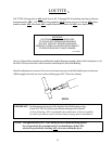
7. Loosen the two (2) set screws in the pillow block bearing and flange bearing. The two (2) set screws on the
flange bearing can be reached through the opening at the bottom of the bearing box.
8. Remove the basket (tumbler) and support assembly from the front of the dryer. If the basket (tumbler)
cannot be removed freely, clean shaft area (with emery cloth) and spray with WD-40 or a similar lubricant.
Use a hammer or mallet to move shaft past any burs made by the set screw.
IMPORTANT:
Never strike the shaft directly with a hammer.
9. Remove four (4) sets of nuts, washers and bolts securing the bearing box assembly to the dryer. Then,
remove the bearing box assembly.
10. Remove four (4) securing the flange bearing to the dryer, then remove the bearing from the dryer. Reverse
procedure for installing new bearing.
11. Reassemble basket (tumbler) and support assembly into the dryer.
12. Reassemble bearing box assembly to dryer.
13. Reconnect belt to idler and motor removed in step 5.
14. Reinstall the front removed in step 4.
15. Make the necessary vertical alignment and lateral alignment adjustments. Follow basket (tumbler) vertical
alignment and basket (tumbler) lateral alignment procedures in sections R and S.
16. Check belt tension and make the necessary adjustments. Follow belt and idler tension adjustment procedures
in section K.
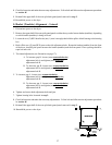
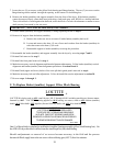
W. To Replace 330º F (Burner) Hi-Limit Switch (Thermostat)
NOTE: The 330º F (burner) hi-limit switch (thermostat) is located on the burner chamber at the rear of the
dryer.
1. Discontinue power to the dryer.
2. Remove the lower half of the split back guard panel to either the top or the bottom basket (tumbler) is being
serviced.
3. Disconnect wiring to the 330º F (burner) hi-limit (thermostat).
4. Disassemble hi-limit from burner chamber by removing the two (2) sheet metal screws securing hi-limit to the
burner box chamber.