


24
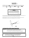
X. To Replace Sail Switch
NOTE: The sail switch and damper is located in the gas valve train assembly.
1. Discontinue power to the dryer.
2. Remove the lint drawer, and the control and lint door. Follow lint drawer, and control and lint door removal
procedures in section II, A and B.
3. Remove sail switch and damper rod assembly from the dryer.
4. Disassemble sail switch bracket assembly from the dryer by removing the two (2) phillips head screws
located in the lint drawer area.
5. Disassemble sail switch bracket assembly from the dryer by removing the two (2) slotted head machine
screws securing the sail switch to the sail switch bracket.
NOTE: When disassembling the sail switch from the bracket, hold on to the twin speed nut located at the
back side of the sail switch bracket into which the screws are threaded.
6. Disconnect the two (2) wires from the sail switch.
7. Reverse steps 3 through 6 for installing new sail switch.
8. Adjust the sail switch by bedning the actuator arm of the switch itself so that when the sail switch damper is
manually closed the sail switch activates and when the damper is released the sail switch deactivates.
9. Reverse steps 1 and 2.
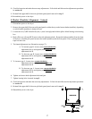
Y. To Replace Main Door Switch
1. Discontinue power to the dryer.
2. Open the main door completely.
3. Remove the two (2) phillips head screws holding the main door switch housing in place.
4. Disconnect the main door switch wires from switch, two (2) yellow wires.
5. Disassemble door switch by removing the two (2) nuts and washers holding the door switch in place.
6. Reverse this procedure for installing new door switch.
IMPORTANT: Under no circumstances should the door switch be disabled.
IMPORTANT: When reinstalling the door switch housing to the dryer, be sure the internal wires do not
get pinched between the door switch housing and the front panel.
7. Reestablish power to the dryer.
Z. To Replace Direct Spark Ignition (DSI) Module
1. Remove the lint drawer, the control and lint door, and the gas valve train assembly from dryer. Follow gas
valve train removal procedure in section C.
2. Disassemble DSI module and bracket assembly from the gas valve train slide by removing the two (2) sets of
nuts and washers securing the bracket to the gas valve train.
3. Disconnect all wiring to the DSI module including the orange high voltage (HV) lead.
IMPORTANT: Identify location of each wire for correct reinstallation.
4. Disassemble DSI module from the bracket by removing the four (4) sets of nuts and washers securing the
DSI module to the bracket.
5. Reverse steps 3 through 5 for installing the new DSI module.