


Assembly Section 2-23
ASSEMBLY
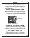
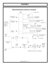
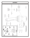
MAIN BOOM INSTALLATION
Install the boom swivel into the main frame as shown in the parts section using a
hoist. Line up holes in swivel and main frame for large swivel pin and insert pin. Secure
with hardware as shown.
Attach the inner end of the main boom to the swivel bracket with the cylinder anchors
positioned upward, and at a right angle to the tractor. Secure it with the horizontal hinge
pin. Secure the hinge pin in the boss with capscrews, etc. (see parts section).
Attach the butt end of the main boom cylinder to the swivel bracket anchor with the
special “bracket head” cylinder pin and roll pin shown in parts section.
Install the travel lock on the butt end of the main boom cylinder. This should be
facing the butt end of the cylinder after installation.
Install the fittings and hoses to the main boom cylinder per parts section.
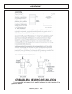
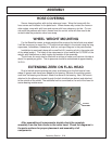
GREASELESS BEARINGS ARE DARK GRAY AND SHOULD NEVER BE
GREASED. THE MAIN BOOM CYLINDER AND THE SECONDARY CYLINDER ARE
NOT GREASELESS AND NEED TO BE GREASED.
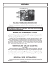
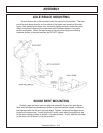
SWITCHING SIDE MOUNT TO BOOM ARM
If you are changing over from a side mounted mower you must first close the ball
valves and remove the motor hoses from the motor to the solenoid valve. Also
remove and replace any fittings that do not match the ones shown in the parts
section diagram.
Next, disconnect all hoses from the control valve. Remove the pin that connects
the lift cylinder to the mast on the main frame. Remove the inner draft beam pin.
At this point the mower should be loose from the tractor.
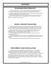
Remove the two spool valve and mount the four spool valve for the boom
according the diagram in the parts section. Also refer to the parts section for the
new hoses that will need to be used.
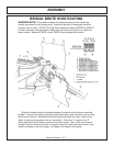
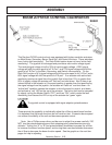
DECK ATTACHMENT
The pivot assembly is used to attach the head to the secondary boom. Install the
deck pivot cylinder using the pins and hardware, which is illustrated in the common
section.
Connect the fittings and hoses from the pivot cylinder to the small preformed
tubes on the boom arm. Connect the fittings and hoses from the motor to the large
preformed tubes on the boom arm. Connect all remaining hoses from the control
valve to the cylinders and / or preformed tubes on the boom arm. Refer to common
section for diagrams.
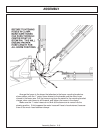
SOLENOID BRAKE VALVE
Install a solenoid valve mounting bracket with the supplied hardware. While
installing fittings to the brake valve, the electrical coil on the spool must be removed to
make room. When reinstalling the coil, it is important to use no more than 5 ft. lbs. (or
60 in. lbs.) torque. Over torque to the coil will result in hydraulic failure of spool.