


Assembly Section 2-9
ASSEMBLY
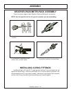
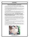
SWITCH BOX WIRING (CABLE)
Refer to the parts section for wiring diagram to hook up the switch box. Cover all
the wires from the switch box with plastic wire wrap provided. Route the wires from
the switch box to the front console panel as shown on previous page. Remove the
console panel under the steering wheel to access tractor wires. Locate the brown
colored wire. Using a test light or meter to verify this wire is the neutral safety
wire. Cut the brown wire and connect the green wires from the switch box as shown
in the wiring diagram.
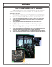
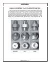
To run the white wire to the solenoid valve, you will need to drill a hole in the front
edge of the cab floor on the right side of the front console. Insert a rubber grommet
into the hole to protect the wire, and route the wire out of the cab.
The red wire is to be hooked to the tractor ignition switch or an available slot in the
fuse box. NOTE: Be certain that the power taken for the switch box is “HOT”
only when the tractor ignition is “ON”. Also double check that the line is
fused.
The travel lock red wire from the switch box should also run with the white wire
through the rubber grommet and be covered with wire wrap. This wire will be
connected to the electronic travel lock located on the main boom cylinder. The wires
from the switch box are longer than needed and should carefully cut and spliced as
required. Zip ties should be used to secure the wires to the tractor framework and
boom hoses to eliminate vibation and rubbing.
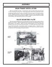
WIRE ACCESS FOR SWITCH BOX (CABLE)
Refer to the parts section for wiring diagrams. Remove right side cowl panel,
tach panel, and hour meter panel for access to the wires.
Route the red wire from the switch box to the bare electrical plug in the fuse box,
or other un-used “keyed” hot wire. NOTE: +12 VOLTS ELECTRICAL POWER
MUST BE TAKEN FROM A SOURCE LOCATION WHERE IT IS LIVE ONLY
WHEN THE IGNITION SWITCH IS IN THE “ON” POSITION.
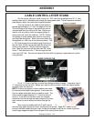
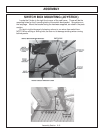
Drill a ½” hole in the 9” X 5” right side panel to route the green & blue safety
switch wires.
The switch box is to be secured to the operators side of the control handles, or
valve stand.
The green & blue wires will connect to the neutral safety switch blue wires,
located on the back of the ignition switch, under the cowl panel.