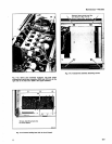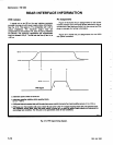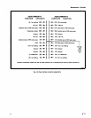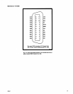
Introduction
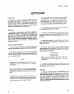
Option
02
provides
r
ear
i
nterface
connections
at
the
r
ear
p
anel
and
O
ption
10 provides
r
ack
mounting
capabilities
.
Information
on
Option
02
is
foundbelow
as
well
as included
i
n
t
he k
it
.
Information
on
Option
10
is
provided
i
n
Section 2
of this
manual
as
well
as
with
t
he
r
ackmount
k
it
available
from
Tektronix,
Inc
.
Option
02
This
factory
installed
o
ption
a
dds
25-mil
square
pin
connectors
to
the
r
ear
of
the
interconnecting
j
acks
at
all
p
ins
from
14
Α
a
nd
Β
to
p
ins
28
Α
a
nd
Β
.
T
his
option
also
adds
six
bnc
connectors
and
o
ne
50-pin
connectorto
the
r
ear
panel
.
These
connectors
are
n
ot
prewired
in
o
rder
to
give as
much
flexibility
as
p
ossible
.
Prepared
jumpers,
coaxial
cables,
and
i
nterconnection
jac
k
b
arriers
are
included
i
n
t
he
k
it
.
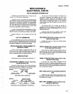
System
Design
Directions
1
.
Plan
the p
lug-in
location
i
n
t
he
mainframe
b
asedon
operator
convenience
as
well as
interface
connections
.
2
.
Plan
thewiring
between
interconnecting
jacks
andto
the
rear
panel
connectors
b
efore
.
starting
assembly
.
Α
m
ating
r
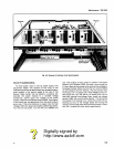
ear
p
anel
50-pin
connector
a
nd
cover
are
provid-
ed
for
external
cabling
.
ΝΟΤΕ
Th
ere a
re
no
p
i
n
assignme
n
ts
fo
r
t
he rea
r
p
a
n
el
conn
ecto
r
s,
due
to
t
he g
reat
var
iety
of
p
ossible
co
nn
ectio
n
s
.
Wh
en
h
ig
h
fr
e
q
uency
o
r
fast
digital
signals
ar
e
i
n
volve
d
,
plan
t
h
e
wi
r
i
n
g
to
m
i
n
imize
crosstalk
.
M
a
k
e
allowa
n
ce
fo
r
p
ossible
au
xilia
r
y g
r
o
und
co
nn
ec-
tions
.
The
50-pin
rea
r
p
a
n
el
co
n
nector
m
ay b
e
easie
r
to
con
n
ect
it
ί 1
is
r
e
m
ove
d
f
r
o
m
t
h
e
r
ear
pa
n
el
a
nd
remo
un
te
d
a
f
te
r
co
nn
ectio
nsa
r
e
ma
d
e
.
R
emove
t
he
to
p
rear ca
b
i
n
et
p
iece
fo
r
ease
of
access
.
OPTIONS
Wire
Use
Sect
i
on
6-TM
5006
If
m
o
r
e
t
h
an
50
p
ins
a
r
e
nee
d
ed,
an
AMP
H
D-22
series
co
n
nector
wit
h
104
pins
may
b
e
m
ou
n
te
d
i
n
t
he sa
m
e c
u
t
o
u
t . i t
is
s
u
ggested
t
hat
t
h
ese
pa
r
ts
be
ob
tai
n
e
d
d
ir
ectly
fr
om
AMP
Inc
.,
H
a
rr
isburg,
PA
o
r
t
h
ei
r
dist
r
ibuto
r
s
.
F
o
r
fu
rt
h
e
r
a
pp
lication
i
n
fo
r
ma-
tion,
co
n
tact
Te
k
tr
on
ix
TM
500
M
a
rk
eting
G
r
o
up
.
3
.
P
in
assignments
for
i
ndividual
p
lug-ins
will
b
e
found
in
t
he
appropriate
instruction
manual
.
4
.
Install
an
interconnection
jack
barrier
at
the ap-
propriate
location
on
the
interconnection
jack
.
R
efer
to
operating
instructions
for
keying
assignments
for
family
functions
.
5
.
Select
and
i
nstall
the
wires
(hook-up
or
coaxial
cable)
following
the
guidelines
in
the
W
ire
U
se
part
of
these
instructions
.
6
.
W
ires
or
cables
which
may
be
at
large
p
otential
d
ifferences
should
be
dressed
o
r
bundled
so
as to
avoid
contact
.
K
eep
all
interface
wiring
away
from
the p
ower
m
odule
primary
line
wiring
.
Maximum
i
npu
t
voltage
is
<
60
Vd
c
or
<
42
.4
Vd
c
p
eak
-to-
p
ea
k
.
Limit
i
np
ut
powe
r
to
<
150
W
pe
r
co
nn
ection
.
7
.
There
is
an
empty
cut
out
which
will
m
ount
the
standard
Ι
E
C
d
igital
interface
connector
.
The
connector
is
n
ot
supplied
with
t
his
option
.
1
.
H
ook
up
wire with
s
quare
p
in
receptacles
on
both
e
nds
.
T
hese
may
be
u
sed
for
lowfrequency
or
do
circuits
where
impedance
levels
and
crosstalk
a
re
n
ot
α
p
roblem
.
The
wire
is
supplied
for
connection
between
com-
partments
(adjacent
or
nonadjacent)
or
b
etween
α
com-
partment
and
t
he
r
ear panel
.
For
connection
to
the
r
ear
panel,
cut
to
length
t
hen
ti
η
a
nd
solder
t
he
end
going
to
t
h
e
rear
p
anel
connector
.


