4
.
Tektron
ix
part
nu
m
be
r
.
Sol
de
r
i
ng
Tec
hn
i
qu
es
W
A
RN
I
N
G
To
avoid
elect
r
ic
s
h
oc
k
haza
rd
,
disconnect
the
i
n
st
rum
e
n
t
f
r
om
t
h
e
power
so
urce
befo
r
e
sol
d
e
r
i
n
g
.
T
h
e
r
elia
b
ility
a
nd
accuracy
of
t
h
is
i
n
str
u
me
n
t
can be
m
ai
n
taine
d
only
if
p
ro
p
er
sol
d
eri
ng
tec
hn
i
qu
es
a
r
e use
d
.
w
h
en
r
ep
ai
r
i
n
g
o
r
r
ep
laci
ng p
arts
.
Ge
n
e
r
al
sol
de
r
ing
tec
h
ni
ques
w
h
ic
h
apply
to
m
ai
n
te
nan
ce
of
any
pr ecisio
n
elect
r
o
n
ic
e
qu
i
p
me
n
t
sh
o
u
l
d
be
u
se
d
w
h
e
nwo
rk
i
ng
on
t
h
is inst
ru
me
n
t
.
U
se
only
60/40
rosin-core,
electronic
g
r
a
de
sol
d
e
r
.
T
he
choice
of
soldering
i
r
o
n
is
dete
rmi ned
by
t
he
r
ep
ai
r
to
b
e
m
ade
.
Wh
en
sol
d
e
r
i
ng
on
ci
r
cu
it
b
oa
rd
s
or s
m
all
wiri
n
g,
u
se
only
α
15
watt,
pencil
ty
pe
sol
d
eri
n
g
iro
n
.
Α
h
ig
h
e
r
wattage
sol
de
r
i
ng
iro
n
can
cause
t
he
etc
h
e
d
circ
u
it
wi
r
i
ng
to
se
pa
r
ate
fr
om
t
he
b
oard
base
m
ater
i
al
and
melt
t
he
i
nsu
latio
n
f
r
o
m
small
wi
r
i
ng
.
Always
k
ee
p
t
h
e
sol
d
e
r
i
n
g
i
r
o
n
ti
p
p
r
op
e
r
ly
ti
nn
ed
to
en
s
ur
ethe
best
heat
t
r
an
sfe
r
to
t
he
sol
de
r
j
oi
n
t
.
A
pp
ly
only e
n
o
ughh
eat to
r
e
m
ove
t
he
com
pon
ent
o
r
to
m
ak
eα
goo
d
sol
d
e
r
j
oi
n
t
.
To
p
r
otect
heat
se
n
sitive
co
mp
o
nen
ts,
h
ol
d
t
he
com
po
nent
lea
d
wit
h
α
p
ai
r
of
lo
n
g-n
ose
p
liers
betwee
n
t
he
co
mp
o
n
e
n
t
bo
dya
nd
t
he
sol
de
r j
oi
n
t
.
U
se
α
sol
d
er
r
e
m
ovi
n
g
wic
k
to
r
emove
excess
sol
d
er
f r
o
m
co
n
nectio
ns or to clea
n
ci
r
cuit
b
oa
rd
pad
s
.
Se
m
i
conductors
To
re
m
ove
i
n
-li
n
e
i
n
tegrate
d
circ
u
its
u
se an
ext
r
acti
ng
tool
.
T
h
is
tool
is
availa
b
le
f
r
o
m
Te
k
tro
n
ix,
Inc
. ;
ord
e
r
Tekt
r
o
n
ix
P
art
No
.
003-0619-00
.
If
an
extracti
ng
tool
is
n
ot
availa
b
le,
use
ca
r
eto
avoi
dd
amagi
n
g
t
h
e
p
i
ns
.
Pull
slowly
a
nd
eve
n
ly
on
b
ot
h
e
nd
s
of
t
h
e
i
n
teg
r
ate
d
circ
u
it
.
Try
to
avoi
dd
ise
n
gagi
ng o
n
e
e
nd
b
efor
e
t
he
other
e
nd
.
M
u
lti
p
i
n
Co
nn
ectors
T
h
e
pin
conn
ectors
u
se
d
to
co
nn
ect
t
he
wires
to
t
he
interconnecting p
i
n
sa
r
e
cla
mp
e
dto
t
he e
nd
s
of
t
h
e
wires
.
To
r
e
p
lace
d
amage
d
m
ulti-
p
i
n
conn
ectors,
r
e
m
ovethe
ol
d
p
i
n co
nn
ecto
r
from
t
he h
ol
de
r
.
Do
t
h
is
b
y
i
n
serti
ng α
sc
r
i
be
betwee
n the
conn
ector
a
nd
t
he
h
ol
d
e
r
a
nd
pr
yi
n
g
t
he
connector
f
r
om
t
h
e
h
ol
d
e
r
.
Cla
mp
t
he
r
ep
lace
m
en
t
co
nn
ector
to
t
he
wi
r
e
.
R
ei
n
stall
t
h
e
conn
ecto
r
in
t
he
h
ol
de
r
.
If
the
i
nd
ivi
du
al
e
nd
lea
dp
i
n
con
necto
r
s
a
r
e
r
emove
d
f
r
o
m
t
he p
lastic
h
ol
de
r
,
n
ote
t
he
order
of
t
h
e
i
nd
ivi
d
ual
wi
r
es
fo
r
correct
r
e
p
lace
m
en
t
i
n
t
h
e h
ol
d
e
r
.
F
o
r
pr
ope
r
r
e
p
laceme
n
t
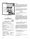
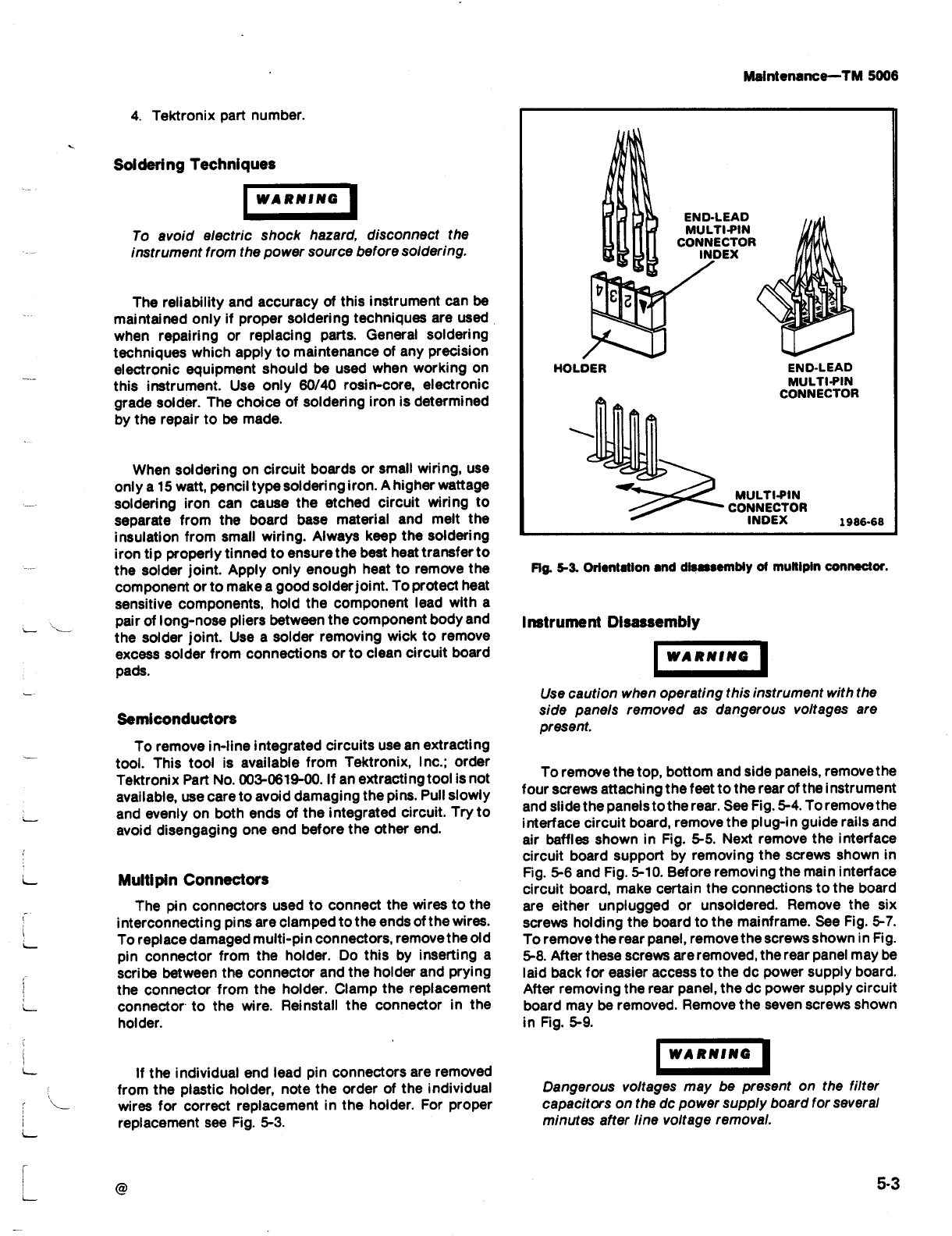
see
F
ig
.
5-3
.
I
n
strument
D
isassem
b
ly
I
WARNING
WARNING
M
a
i
n
te
n
ance-
ΤΜ
5006
H
O
LD
ER
EN
D-
LE
AD
MUL
TI-PIN
CO
NNECTO
R
EN
D-
LE
AD
MUL
TI-PIN
CO
NNECTO
R
IN
D
E
X
MUL
TI-PIN
CO
NNECTO
R
IN
D
E
X
1986-68
Fig
.
5-3
.
Orientation
a
nd d
isasse
mb
ly
of
mu
ltip
in
connector
.
U
se
cautio
n
w
h
en
o
p
e
r
ati
n
g
t
h
is
inst
ru
me
n
t
wit
h
t
h
e
si
d
e pa
n
els
r
e
m
ove
d as d
a
n
ge
r
o
u
s
voltages
a
r
e
pr
ese
n
t
.
To
r
e
m
ove
t
he
to
p
,
b
ottom
a
nd
si
d
e
p
a
n
els,
r
emove
t
he
fo
u
r
sc
r
ews
attac
h
i
n
g
t
he
feet
to
t
he
r
ea
r
of
t
he
i
n
st
ru
me
n
t
a
nd
slide
t
he
pa
n
els
to
t
he
r
ea
r
.
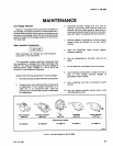
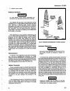
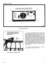
See
F
ig
.
5-4
.
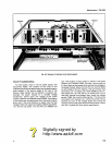
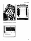
To
remove
t
h
e
interface
ci
r
cu
it
b
oar
d
,
r
e
m
ove
t
h
e p
l
u
g-i
n
gui
de
r
ails
a
nd
air
baffles
s
h
ow
n
in
F
ig
.
5-5
.
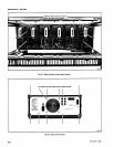
N
ext
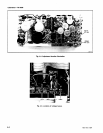
r
emove
t
h
e
interface
ci
r
cu
it
b
oa
rd su
pp
ort
b
y
r
e
m
ovi
ng
t
h
e
sc
r
ews
s
h
ow
n
in
Fig
.
5-6 a
nd
F
ig
.
5-10
.
B
efo
r
e
r
e
m
ovi
ng
t
h
e
mai
n
interface
circ
u
it
b
oa
rd,
m
a
k
e
certai
n
t
he
co
nn
ectio
n
sto
t
h
e b
oar
d
a
r
e
eit
he
r
unp
l
u
gge
d
o
r
un
sol
de
r
ed
.
Re
m
ove
t
he
six
screws
h
ol
d
i
n
g
t
h
e
boa
rd to
t
he
m
ai
n
fra
m
e
.
See
F
ig
.
5-7
.
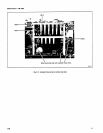
To
r
e
m
ove
t
h
e
r
earpa
n
el,
r
emovet
he
screws
sh
ow
n
in
F
ig
.
5-8
.
Afte
r
t
h
ese
screws
are
r
e
m
ove
d
, t
he
rear
p
a
n
el
may
b
e
laid
back fo
r
easie
r
access
to
t
h
e
d
o
powe
r
s
upp
ly
b
oa
rd
.
After
re
m
ovi
n
g
t
he
r
ea
r
pan
el,
t
h
e
do
power
s
upp
ly
circ
u
it
b
oa
rd
m
ay
b
e
remove
d
.
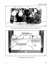
R
emove
t
h
e seve
n
sc
r
ews
sh
ow
n
in
Fig
.
5-9
.
Da
n
gero
us
voltages
may
b
e
p
r
ese
n
t
on
t
h
e
filte
r
ca
p
acito
rs
on
th
e
d
o
p
owe
r
s
upp
ly
boa
rd
fo
r
seve
r
al
minutes
afte
r
line
voltage
r
emoval
.
5-3


