TM
5006
IV
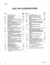
LIST
OF
ILLUSTRATIONS
Page
Oute
r
p
a
n
el
removal
. . . .
.
. . .
. .
. .
. .
5-4
G
u
i
de
rail
a
nd
air
b
affle
removal
. .
. . .
5-4
R
e
m
oval
of
i
n
terface
ci
r
cuit
boa
rd
s
upport
. . . . . . . .
.
. . .
. . . . . . . . . .
.
5-5
M
ai
n
i
n
terface
ci
r
cu
it
b
oar
d
r
e
m
oval
.
.
5-6
R
ea
r
p
an
el
r
e
m
oval
. . . . . . .
.
.
.
.
. . . .
5-6
L
ocatio
n
of
screws
h
ol
d
i
ng
t
he
dc
power
s
up
ply
circ
u
it
b
oar
d to
t
h
e
mai
n
f
r
a
m
e
ch
assis
. .
.
. . . . .
.
.
.
. . . .
. . .
.
. .
.
. .
5-7
Attach
i
n
g
screws
on
b
otto
m
of
m
ai
n
f
r
a
m
e
. . . . . . . . . .
.
. . . .
. . . . .
.
5-7
Un
sol
de
r
t
h
ese
wi
r
es
to
r
e
m
ove
h
eat
si
n
k
.
. . .
. .
. . . . . .
.
. .
. .
.
. . . .
5-8
Se
r
ies
p
ass
t
r
a
n
sisto
r
locatio
ns
.
T
he
h
ig
h
p
owe
r
co
mp
art
m
en
t
series
pass
t
r
a
n
sisto
r
s
0600
a
nd
0610
a
r
e
on
t
he
r
ig
h
t
si
de
of
t
he
h
eat
si
nk
.
0600
is
t
he
uppe
r
transistor
. . . . . . . .
. . .
.
. . . . .
.
. . .
.
5-9
Sc
r
ews
h
ol
d
i
n
g
h
eat
si
nk
to
ci
r
cu
it
b
oa
rd
. .
. . . . . . . .
. . . .
.
.
. . . .
.
. . .
5-9
T
r
a
n
sfor
m
e
r
asse
mb
ly
attac
h
i
ng
scr
ews
.
. .
. .
.
. . .
. . . .
. .
.
. .
.
. . .
.
.
5-9
PWR
sig
n
al
ti
m
i
n
g d
iag
r
a
m
. .
.
. .
.
. . .
5-10
Rea
r
i
n
te
r
face
connector
assig
nm
en
ts
.
5-11
R
ea
r
panel
G
P
I
B
connector
J
1110
viewed
fro
m
r
ear
of
power
m
o
du
le
(IEEE
Sta
nd
a
rd
No
.
488)
. . .
.
. .
.
.
. .
.
. . . .
5-12
Dc
p
owe
r
s
upp
ly
b
oa
rd
(
Α
11)
Dc
p
owe
r
s
upp
ly
r
eg
u
lato
r
wavefo
rm
s
M
ai
n
i
n
terface
b
oa
rd
(
Α
10)
G
P
I
B
i
n
terco
nn
ect
b
oa
rd
(
Α
16
b
ack
si
d
e)
REV
N
O
V
1984
Fig
.
No
.
TM
5006
Power
Module
.
.
.
. . . . . .
. .
P
age
viii
F
ig
.
No
.
5-4
21
TM
5006
rear
panel
. . . . . . . . . . . . .
. .
2-2 5-5
2-2
TM
5006
fro
nt
view
. .
.
. .
.
. . . . .
. . .
.
2-3 5-6
2-3
TM
5006
b
otto
m
view
.
. . . .
. .
.
. . . .
.
2-4
2-4
TM
5006,
O
p
tio
n
10
overall
d
i
m
en
sio
ns
2-5
5-7
2-5
R
ac
k
latc
h
h
ole
. .
.
. . . . . . . . . . . . . .
2-6
5-8
2-6
Di
m
e
n
sio
ns a
nd
p
ositio
n
i
n
g
of
TM
5006,
5-9
Optio
n
10,
i
n
sta
nd
a
rd
rac
k
. . . . . . . . .
2-7
2-7
Rac
km
o
un
t
sli
de
d
etail
.
If
t
he
r
ac
k
has
tapped
h
oles,
t
h
e
b
ar
n
uts
a
r
e n
ot
5-10
required
. . . . . . . .
.
. . . . . .
.
. . . . .
.
2-8
2-8
R
ac
km
o
un
ti
n
g
sli
de
d
etails
.
.
. . . . . . .
2-8
5-11
29
Re
m
ovi
ng
and
i
n
stalli
ng
TM
5006,
O
p
tio
n
10,
i
n
r
ac
k
sli
d
es
. .
. .
. . .
.
. . . . . . . .
2-9
5-12
2-10
Pl
u
g-i
n
i
n
stallatio
n
a
nd
re
m
oval
. . . . . .
2-10
211
K
eyi
ng
assig
nm
e
n
ts
forfa
m
il
y
f
un
ctio
n
s
.
One
of
t
he
m
an
y
p
ossi
b
le
sequ
e
n
ce
com
b
i
n
atio
n
s
. . . .
. . . .
.
. .
. . . . . . . .
2-10
3-1
Various
waveformsa
nd
time
relationships
5-13
fo
r
powe
r
on,
off,
fa
u
lt,
a
nd
low
li
n
e
. . .
3-2
3-2
I
npu
t
li
ne
conn
ectio
n
sfo
r
110
V
a
nd
220
V
5-14
operation
. . .
.
. . . . .
.
. .
.
. . .
. . . .
.
.
3-3
4-1
P
ossi
b
le
loads
for
u
se
i
n p
erfo
rm
a
n
ce
5-15
chec
k p
r
oce
dur
e
.
See
te
x
t
.
.
.
. . . . . . .
4-1
5-16
42
Test
set
u
p
fo
rperfo
r
m
a
n
ce
check
steps
1,
5-17
2a
nd
3a
nd
locatio
n
of
conn
ectio
ns
fo
r
a
dj
ust
m
en
t
ste
p
1
.
. .
. .
.
. .
.
. . . . . . .
44
4-3
Loa
d
s
fo
r
use
i
n
i
n
ternal
8-1
a
dju
st
m
e
n
t
pr
oce
du
re
. .
. .
. . . . . . . . .
.
. . .
4-5
8-2
4-4
A
dj
ust
m
en
t
locatio
n
ill
u
st
r
atio
n
. . . . . .
. .
.
.
4-6
4-5
Locatio
n
of
voltage
b
uses
. . . . . . . . . . . .
.
.
4-6
8-3
5-1
L
i
ne
cord o
p
tio
ns
fo
r
t
h
e
TM
5006
. . . .
5-1
8-4
5-2 L
i
n
e
voltage
jump
er p
ositio
ns
. . . . . . .
5-2
5-3
O
r
ie
n
tatio
n
a
nd
d
isasse
mb
ly
of
mu
lti
p
i
n
conn
ecto
r
s
. . . .
. .
. .
.
.
.
. . . . .
.
. . .
5-3


