Ope
r
ati
n
g
Instructions-TM
5006
L
i
ne
f
u
se holder
P
o
w
e
r
co
rd
r
ecep
tacle
R
ea
r
i
n
ter
f
ace
bnc
co
nn
ecto
r
s
(Op
tio
n
02
on
ly)
Access
pa
n
el
fo
r
ca
b
li
ng
to
f
r
o
n
t
of
po
w
e
r
m
odu
le
2950-01
T
he
sli
de-o
u
t
trac
k
s,
w
it
h
existing
ha
rd
ware
s
upp
lied,
will
conve
n
ientl
y
mo
u
nt in
any
r
ack
wit
h
t
hef
r
o
n
t
a
nd
rea
r
rails
space
d
f
r
om
10
1/2 inc
h
es to
24 1/2
i
nc
h
es
.
Mounting
t
he
Sli
de
T
r
ac
k
s
.
L
ocate
t
h
e p
r
oper
r
ac
k
h
oles
fo
r
m
ou
n
ting
as
show
n
in
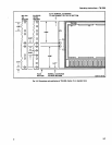
F
ig
.
2-6
.
N
otice
t
h
at
t
h
e
h
olespacing
in
t
he
rac
k
s
va
r
ies
.
Wh
en
installing
t
he
slides
i
η
t
he
Ε
1
Α
ty
pe
r
ac
k
s,
ma
ke
certain
t
h
e
sli
d
es
are
attac
hed
tot
h
e
1/2-i
n
ch
space
d
h
oles
.
Figure
2-6
also
shows
details
fo
r
dete
r
mini
n
g
p
ositio
n
of
t
he
slides
i
n
the
r
ack
.
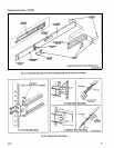
Mount
t
h
e
r
ails
u
si
n
g
e
nclosed
h
a
r
d
w
a
r
e
as
sh
o
w
n
in
F
igs
.
2-7
and
2-8
.
F
ig
ures2-8
Ba
nd
Cshow
rail-mounting
d
etailsfor
d
eep
a
n
d
s
hallowrac
k
s
.
Make
s
u
r
eth
estationary
sections
a
r
e
h
orizo
n
tally
alig
ne
d
sot
hey a
r
e
level
a
nd
pa
r
allel
wit
h
each
ot
h
e
r
.
Installing
the
TM
5006,
Option
10,
in
the
Rack
Slides
.
M
a
ke
certain
all
p
lug-ins
are
remo
v
ed
from
t
he p
owe
r
mo
d
ule, Pull
the
slide-out
trac
k
inte
r
me
d
iate
sectio
n
s
ou
t
as
far
as
t
h
e
y
will
go
.
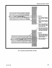
See
Fig
.
2-9
.
Inse
r t
the
i
n
strument
chassis
sectio
ns
i
n
to
t
h
e
intermediate
section
an
d
push
t
h
e
inst
r
ument
fo
r
w
ar
d un
til
t
he
instrument
c
h
assis
sec-
tio
n
loc
ks
i
n
to
t
he
inte
r
m
ed
iate
sectio
n
.
Now
pr
ess
bot
h
b
utto
n
s
protruding
fro
m
t
he
sto
p
-latc
h
h
oles
i
n
t
h
e
i
n
te
r
m
ed
iate
sectio
ns
w
h
ile
pu
s
h
i
ng
t
he
i
n
st
r
u
me
n
t
.
T
he
i
n
st
r
um
e
n
t
can
now
b
e
pu
sh
e
d
i
nto
t
he
rac
k
,
ca
b
inet,
o
r
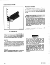
20-2
F
i
g
.
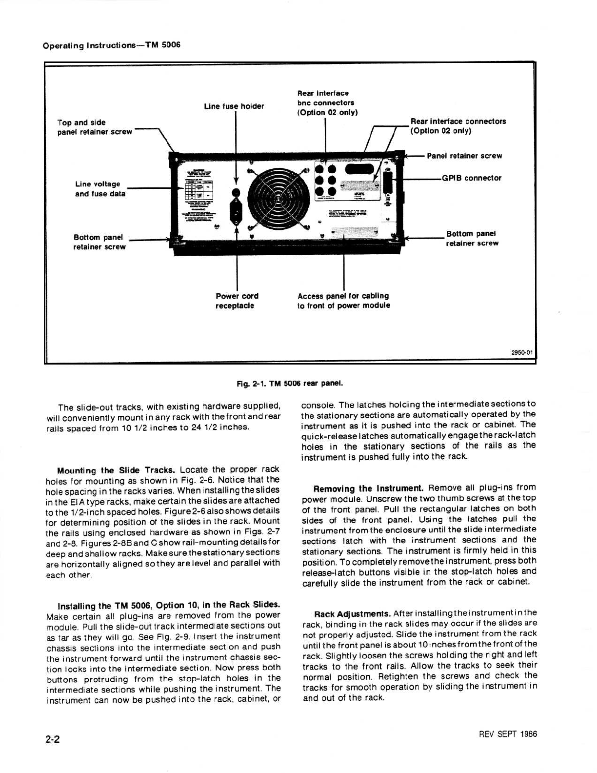
2-1
.
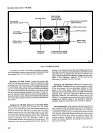
TM
5006
r
ea
r
panel
.
co
n
sole
.
T
h
e
latc
hes
h
ol
d
ing
t
he
i
n
te
r
m
e
d
iate
sectio
n
s
to
t
h
e
statio
na
r
y
sectio
ns a
r
e
a
uto
m
aticall
y ope
r
ate
d
b
y
t
h
e
instru
m
e
n
t
as
it
is
p
us
h
ed
into
t
he
rac
k
or
cab
i
n
et
.
T
h
e
qu
ic
k
- r
elease
latc
hes au
tomaticall
y
e
n
gage
the
r
ac
k
-latc
h
h
oles in
t
he
statio
na
r
y
sections
of
t
he
rails
as
t
he
i
n
str
um
e
n
t
is
pu
s
hed
fully
i
n
to
t
he
r
ack
.
Removi
n
g
t
he
I
n
st
r
ument
.
R
e
m
ove
all
p
l
u
g-i
ns
f
r
o
m
power
mo
du
le
.
Un
scre
w
t
he
t
w
o
t
hu
m
b
sc
r
e
w
s
0-t
t
hetop
of
t
he
f
r
o
n
t
panel,
Pull
t
he
r
ectang
u
la
r
latc
hes on
b
ot
h
sides
of
t
he
fro
n
t
p
an
el
.
Using
t
he
latc
h
es
pull
the
instrume n
t
from
t
he
e
n
closu
r
e u
ntil
t
he
sli
de
inte
r
me
d
iate
sectio
ns
latc
h
w
it
h
t
he instrument
sectio
n
s an
d
t
he
statio
na
r
y
sectio
ns
.
T
he
i
n
st
r
um
ent
is
fi
r
m
l
y
held
in this
p
osition
.
To
com
p
letely
r
e
m
ovet
h
e
i
n
st
ru
ment,
p
r
essbot
h
release-latc
h
b
u
tto
n
s
visi
b
le in
t
he
stop-latc
h h
oles
and
caref
u
lly
slide
t
h
e
instrument
f r
om
t
he rac
k
o
r
ca
b
i
n
et
.
R
ack
Ad
j
ust
m
e
n
ts
.
Afte
r
installing
t
he
i
n
st
r
um
ent
ί
η
th
e
r
ack,
bi
n
d
ing
in
the
r
ac
k
sli
d
es
may
occ
u
r
if
t
he
sli
des
are
not
pr
operl
y
ad
j
u
ste
d
.
Sli
d
e
t
he
i
n
st
r
um
ent
f r
om
t
he
rac
k
until
t
he
f
r
on
t
panel
is
a
bo
u
t
10
i
nc h
es
f
r
om
t
h
e
f r
on
t
of
the
r
ack
.
Slig
h
tl
y
loosen
t
he sc
r
e
w
s
hol
d
i
n
g
t
he
rig
h
t
an
d
left
t
r
acks
to
t
h
e
fro
n
t
rails
.
Allow
t
h
e
tr
acks
to
see
k
t
h
eir
nor
m
al
p
ositio
n
.
R
etig
h
ten
t
h
e
screws
and c
h
ec
k
t
he
trac
k
s
fo
r
s
m
oot
h
op
e
r
atio
n by
slidi
ng
t
h
e
i
n
st
r
u
m
en
t
in
an
do
u
t
of
t
h
e
r
ack
.
R
EV
S
E
P
T
1966


