Ope
r
ati
n
g
Inst
ru
ctions-T
M
5006
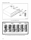
compartments
to
accept only
m
embers
of that
family,
b
y
installing
α
second
barrier
in
t
he
interface
connector
to
match
t
he
m
odule's
slot
location
.
An
entire
TM
5006
can
be
set
up
in
t
his
m
anner
for
s
pec
i
fic
work
f
unctions
.
For
extra
b
arriers,
order
Tektronix
Part
No
.
2141593-02
.
R
ear
Panel
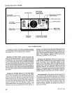
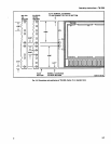
The
r
ear p
anel
has α
connector
m
ounting
p
late
for
bnc
and
multi-pin
connector
m
ountings
.
Customer
o
ι
factory-
installed
connectors
and
wiring
(Option
02)
can
p
rovide
external
access
to
the
interface
.
This
feature
makes
the
TM
5000-Series
M
odular
Instrumentation
System
very
flexible
in
bench-top
or
rackmounted
systems
.
Option
02
Q
ualified
service
p
ersonnel
see
Section
6
in
t
he
Ser
v
ice
section
of
this
manual
for
information
on
O
ption
02
.
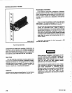
2-6
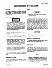
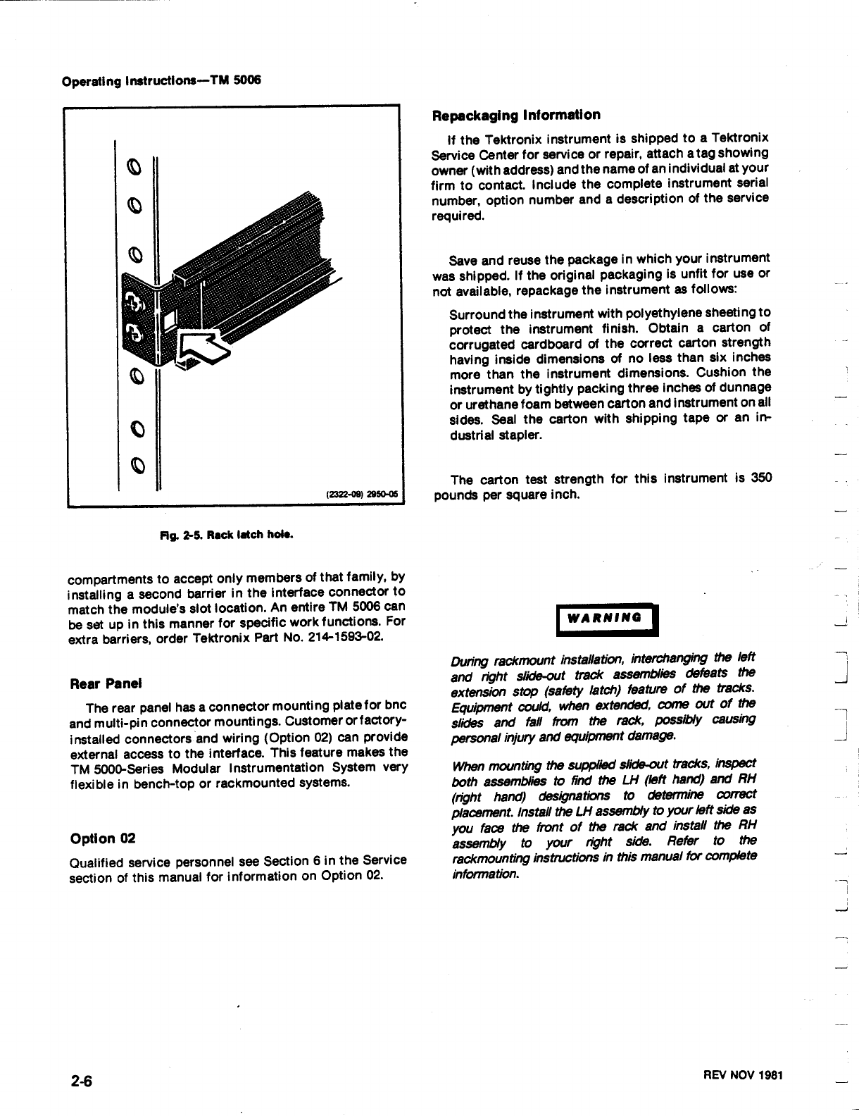
F19
.
2-5
.
R
ack
latch
hole
.
R
epac
k
agi
n
g
I
n
fo
r
mat
i
o
n
If
t
h
e
Tektro
n
ix
i
n
st
ru
me
nt
is
s
h
i
p
pe
d
to
α
Tekt
r
o
n
ix
Service
Ce
n
ter
for
service
o
r
re
pai
r
,
attac
h
α
tag
s
h
owi
n
g
owner
(with
a
ddress)
and
the
n
ame
of
an
individual
at
your
firm
to contact
.
Include
the
complete
instrument
serial
number,
option
number
a
nd
α
d
escription
of
the
service
r
equired
.
Save
and
reuse
the
package
in
w
hich
your
instrument
was
shipped
.
If
the
original
p
ackaging
is
unfit
for
u
se
or
not
available,
repackage
the instrument
as
follows
:
Surround
t
he
instrument
with
polyethylene
sheeting to
protect
the instrument
finish
.
Obtain
α
carton
of
corrugated
cardboard
of
the
correct
carton
strength
having
inside
d
imensions
of
no
less
than
six
inches
m
ore
than
t
he
instrument
dimensions
.
Cushion
t
he
instrument
b
y
tightly
p
acking
three inches
of
dunnage
or
urethane
foam
between
carton a
nd
instrument
on
all
sides
.
Seal
the
carton
with
s
hipping tape
or
an
in-
dustrial
stapler
.
The
carton
test
strength
for
t
his
instrument
is
350
pounds
per
square
inch
.
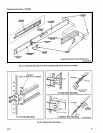
W
A
RN
I
NG
During
r
ackmou
n
t
installation,
interchanging
t
left
an
d
r
ig
h
t
sl
ί
d
e-o
u
t
trac
k
assemblies
de
f
eats
t
he
extension
sto
p
(safety
latc
h
)
featur
e
of
t
he
trac
k
s
.
Equipment
cou
l
d
,
w
he
n
extende
d
,
come
out
of
t
he
slides
and
fall
from
t
h
e
r
ac
k
,
p
oss
ί
b
ly
cau
sing
p
erso
ηα
l i
nj
ury
and
equipment
da
m
age
.
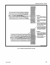
Wh
e
n
mounting
t
hesu
ppl
ί
e
d
slide-o
u
t t
r
acks,
i
n
s
p
ect
b
ot
h
assemblies
to
find
t
h
e
LH
(left
ha
nd)
a
nd
RH
(ng
h
t
han
d
)
designations
to
dete
r
m
i
n
e
correct
placeme
n
t
.
Install
t
he
LH
asse
m
bly to
yo
ur
left
si
d
eas
yo
u
face
t
h
e
fro
n
t
of
t
he
rack
and
i
n
stall
the
RH
asse
m
bly
to
you
r
r
ig
h
t
s
ί
d
e
.
R
efer to
t
he
r
ack
mo
un
ti
η
g
ί
n
sin
r
ctions
in this
ma
nu
al
for
complete
information
.
REV
NOV
1981


