Introduction
T
h
e
TM
5006
Power
M
o
du
le
is
cali
b
rate
d
a
nd
r
ea
d
yfo
r
use
w
hen
r
eceive
d
.
Α
list
of
sta
nd
a
rd
accessories
(a
nd
part
nu
mb
e
r
s)
is
locate
d
in
t
h
e
back
of
t
h
is
m
a
nu
al
.
P
owe
r
So
u
rce
R
eq
u
i
r
eme
n
ts
AC
P
O
WER
SOUR
C
E
A
ND
CO
NNE
CTIO
N
.
Th
is
inst
rum
e
n
t
operates
f
r
om
α
si
n
gle-
ph
ase
powe
r
source
.
It
h
as α
three-wire
p
owe
r
co
rd
an
d
two-
p
ole,
thr
ee-ter
m
inal
grounding-type
pl
ug
.
T
h
e
voltage
to
g
r
ou
n
d
(eart
h
) fr
om
either
p
ole
ο
/
t
h
e
powe
r
so
u
rce
mu
st
not
excee
d
t
h
e
maxi
mu
m
rated
op
er
ati
ng
voltage,
250
V
.
Before
mak
i
ng
con
n
ectio
n
to
t
h
e
power
sou
r
ce,
dete
r
mi
n
e
t
h
at
t
he
instrument
is
a
d
juste
d
to
m
atc
h
t
h
e
voltage
of
t
h
e
powe
r
sou
r
ce,
a
ndh
as
a
suitable
two-pole,
t
hr
ee-te
rm
ί
n
alg
r
o
und
i
n
g-type
p
l
ug
.
R
e
f
e
r
any
c
h
a
n
ges
to
qu
alif i
e
d
se
r
vice
pe
r
so
n
nel
.
GR
O
UN
DI
NG
.
T
h
is
instrument
is
safety
class
Ι
e
qu
i
pm
ent
(
ΙΣ
C
designation)
.
All
accessi
b
le
con-
du
ctive
parts
a
r
e
directly
co
nn
ecte
d
t
hr
oug
h
t
h
e
grounding
con
du
cto
r
of
t
h
e
p
owe
r
co
rd
to
t
h
e
grounding
co
n
tact
of
t
he
powe
r
p
l
u
g
.
T
he
powe
r
i
np
ut
p
l
ug
m
u
st
only
be
inserted
in
a
mating
r
ece
p
tacle
wit
h
α
gro
und
ing
co
n
tact
.
Do
n
ot
defeat
t
he
grounding
con
n
ectio
n
.
A
ny
interruption
o
f
t
he
grounding
connection
can
create
an
elect
r
ic
shoc
kh
azard
.
Fo
r
elect
r
ic
s
h
ock pr
otection,
t
h
e
grounding
con-
nection
m
u
st
be
ma
d
e
b
efo
r
e
ma
k
i
ng
connection
to
t
h
e
inst
ru
me
n
t's
in
pu
t
o
r
out
pu
t
terminals
.
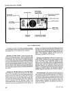
See
Fig
.
2-1
.
R
efe
r
to
t
he
li
n
e
voltagea
nd
I
use
d
ata
la
b
el
on
t
h
e
r
ear
p
an
el
.
Fu
se
R
e
p
lace
m
e
n
t
T
urn
t
h
e
slotte
d
sectio
n
of
t
he
li
n
e
fuse
h
ol
d
er
coun
te
r
cloc
kwise a
nd
r
e
m
ove
t
h
e
f
use
.
R
ep
lace
t
h
e
f
u
se
wit
h
t
he
pr
o
pe
r
ty
pe
as s
h
ow
n
on
t
he
r
ea
r
p
an
el
la
b
el
.
Ca
b
li
ng
R
e
m
ove
powe
r
co
rd befo
r
e
attempting ca
b
le
in-
stallation
.
F
o
r
con
ve
n
ie
n
ce,
ca b
li
ng
f
r
o
m
t
h
e
fro
n
t
of
t
he
p
owe
r
m
o
du
letot
h
e
rear
panel
m
ay
b
e
run
t
hr
o
ug
h
t
he
ai
r
i
n
ta
k
e
REV
N
O
V
198
3
O
PER
ATI
N
G
I
N
ST
RU
CTIO
N
S
ΙΝΑ
RM
1
ΝG
a
nd ca
b
le
raceway
as
s
h
ow
n
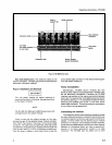
in
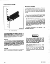
F
ig
.
2-2
.
To
i
n
stall
t
h
is
ca
b
li
ng
first
r
e
m
ove
t
he
access
pa
n
el
on
t
h
e
rea
r
of
t
he
power
m
o
du
le
.
See
Fig
.
2-1
.
N
ext
r
e
m
ove
t
h
e
two
b
ottom
p
a
n
el
r
etai
ne
r
sc
r
ews
a
nd
t
he
b
otto
m
pa
n
el
retai
ne
r
s
.
Sli
de
t
h
e b
otto
m
pan
el
o
u
t
fro
m
t
he
r
ea
r
of
t
h
e
i
n
str
u
me
n
t .
P
ass
t
he
ca
b
le
t
hr
o
ug
h
t
h
e
f r
o
n
t
ai
r
i
n
ta
k
e,
ac
r
oss
t
he
botto
m
of
t
he
p
l
u
g-i
n
s
upp
ort
r
ails
a
nd
o
u
t t
h
e
access
p
an
el
.
R
e
p
lace
t
he p
ower
m
o
du
le
b
ottom
cover
.
Ta
b
le
Top
U
se
To
e
n
su
r
e
pr
ope
r
cooling,
do
not
o
p
erate
t
h
e p
owe
r
m
o
d
ule
wit
h
any
cover
remove
d
.
T
he
powe
r
m
o
du
le
m
ay
b
e ope
r
ate
d
wit
h
t
he
fro
n
t
r
aise
d
.
To
r
aise
t
h
e
f
r
on
t
of
t
he
i
n
str
u
me
n
t
exte
nd
t
he
fro
n
t
b
ail
as
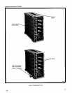
s
h
ow
n
in
F
ig
.
2-3
.
R
ac
km
o
un
ti
n
g
Instructions
Sectio
n
2-TM
5006
Cooli
ng
.
E
x
a
m
i
ne
the
si
de
p
a
n
els
of
t
he
TM
5006,
O
p
tio
n
10,
powe
r
m
o
du
le
.
If
the
r
e
are
no
cooling
h
oles
i
n
t
he
si
de
p
a
n
els,
at
least
1-i
n
ch
clea
r
ance
m
u
st
b
e
m
ai
n
tai
ned
b
etween
the b
ottom
of
the
powe
r
m
o
du
le
a
nd
t
he
i
n-
stru
m
en
t
below
it
.
T
h
is is
necessary
to
i
ns
ur
e
p
rope
r
cooling
.
If
t
h
e
si
d
e
p
a
n
els
h
a
v
e
cooli
n
g
h
oles,
no
special
p
recautio
n
sa
r
e
n
ecessary
.
If
t
h
e
r
ack has
positive
i
n
ternal
pr
ess
ur
e
for
cooli
n
g
pu
rposes,
t
he
mai
n
frames
mu
st
h
ave
all
co
mp
artme
n
ts
fille
d
wit
hp
l
u
g-i
n
s
o
r
b
la
nk
f
r
on
t
p
anels
(availa
b
le
fro
m
Te
k
t
r
o
n
ix,
I
nc
.)
must
b
e
i
n
stalle
d
in
t
h
e
unused
p
l
u
g-i
n
ope
n
i
n
gs
.
If
g
r
eate
r
i
n
ternal
air
flow
is
d
esi
r
ed
in
α
r
elatively
h
ig
h
ly
pr
ess
ur
ize
d
r
ac
k,
t
heg
r
ill
ope
n
i
n
g
at
the
b
ottom
fr
o
n
t
of
t
he
-TM
5006
m
ay
also
b
e
b
loc
k
e
d
.
R
ac
k
Di
m
e
n
sio
ns
.
T
h
e
TM
5006,
O
p
tio
n
10,
is
sh
i
p
pe
d
f
r
o
m
t
h
e
factory
r
ea
d
y
fo
r
rack
m
o
un
ti
n
g
.
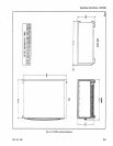
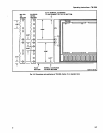
Figure
2-4 sh
ows
ma
j
o
r
d
i
m
e
n
sio
n
s
.
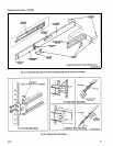
F
t
u
re
2-5 s
h
ows
t
h
esp
ri
n
g-latc
h
c
u
tout
i
n
t
he
stationary
sectio
n
.
ΝΟΤΕ
The
sli
d
e
t
r
ac
k
s
supp
lied
wit
h
t
he
TM
5006,
Op
tio
n
10,
h
ave
h
oles
in
the
stationary
sectio
ns
to
acco
m
o
d
ate
t
h
e
spri
n
g
latc
h
es
.
Th
e
TM
5006,
Op
tio
n
10,
should n
ot
be
mo
u
nted
wit
h
r
ac
k
slides
t
h
at d
o
n
ot
h
ave
t
h
e
r
ac
k
-latc
h
h
oles
.
T
h
e
TM
5006,
O
p
tio
n
10,
fits
t
he
sta
nd
a
rd
19-i
nch
si
d
e
ca
b
i
n
et,
r
ack o
r
co
n
sole
.
Sp
aci
ng
i
n
si
de
t
he
fr
on
t
r
ails
mu
st
be
at
least
17
3/4
i
n
c
h
es
.
T
h
is
allows clea
r
a
n
ce
fo
r
t
he
statio
n
ary
sectio
n
of
t
h
e
sli
d
e-o
u
t
t
r
acks
to
p
ermit
t
he
assem
b
ly
to
sli
de
fr
eely
on
t
he
sli
d
-o
u
t tr
ac
ks
.


