Appendix B: Operator Performance Checks
B–10
1502C MTDR User Manual
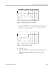
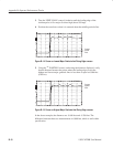
3. Turn the VERT SCALE control clockwise until the leading edge of the
incident pulse is five major divisions high (about 205 mr).
4. Position the waveform so that it is centered about the middle graticule line.
O
F
F
O
F
F
O
F
F
O
N
ac –0.848 ft
Crosses
Lowest
Point
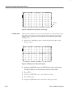
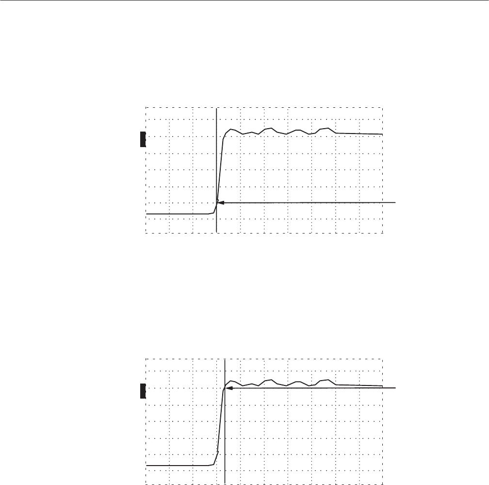
Figure B–14: Cursor on Lowest Major Graticule that Rising Edge crosses
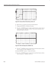
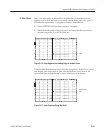
5. Using the
n
o
POSITION control, and noting the distances displayed, verify
that the distance between the points where the leading edge crosses the
highest and lowest major graticule lines is less than or equal to 0.096 feet
(0.029 m).
O
F
F
O
F
F
O
F
F
O
N
ac –0.768 ft
Crosses
Highest
Point
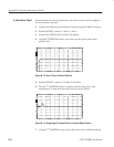
Figure B–15: Cursor on Highest Major Graticule that Rising Edge crosses
In the above example, the distances are –0.848 feet and –0.768 feet. The
difference between these two measurements is 0.080 feet, which is well within
specification.


