Operating Instructions
1502C MTDR User Manual
1–5
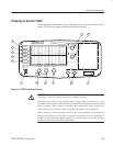
Preparing to Use the 1502C
Check the power requirements, remove the front cover, and you are ready to test
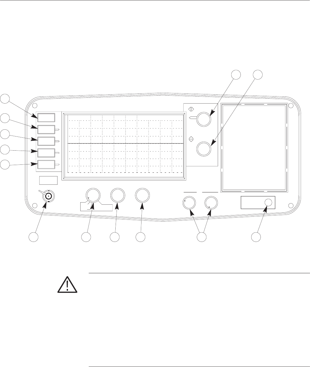
cables. The following pages explain the front-panel controls.
O
F
F
O
F
F
O
F
F
O
N
1 avg
500 mr
ac 0.00 ft
MENU
VIEW
INPUT
VIEW
STORE
VIEW
DIFF
STORE
POSITION
DO NOT APPLY
POWER
(PULL ON)
POSITION
NOISE FILTER VERT SCALE DIST/DIV
SET REF
HORZ
VERT
.3
.4
.5
.6
.7
.8
.9
.00
.01
.02
.03
.04
.05
.06
.07
.08
.09
Vp
METALLIC TDR
CABLE TESTER
1502C
Tektronix
1
3 4 5 6
7
9
10
11
12
13
0.2 ft
2
8
EXT VOLTAGE
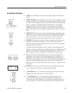
Figure 1–3: 1502C Front-Panel Controls
CAUTION. Do not connect live circuits to the CABLE connector. Voltages
exceeding 5 volts can damage the pulser or sampler circuits.
Bleed the test cable of any residual static charge before attaching it to the
instrument. To bleed the cable, connect the standard 50 W terminator and standard
female-to-female BNC connector together, then temporarily attach both to the
cable. Remove the connectors before attaching the cable to the instrument.
When testing receiving antenna cables, avoid close proximity to transmitters.
Voltages may appear on the cable if a nearby transmitter is in use, resulting in
damage to the instrument. Before testing, be sure that there are no RF voltages
present, or disconnect the cable at both ends.


