Appendix D: Application Note
D–8
1502C MTDR User Manual
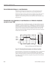
Dielectric Constant vs. Velocity Factor
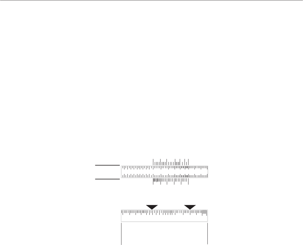
Dielectric Constant and Velocity Factor appear on two identical scales next to a
sliding scale labeled ROUND TRIP TIME. To find one, knowing the other, read
across the sliding scale. Any major division on the sliding scale can be placed
next to the known value to help read directly across the sliding scale.
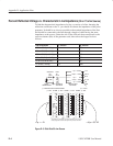
Time vs. Short Distances, in Centimeters or Inches (any dielectric)
To find the distances to or between discontinuities in a transmission line,
knowing the time for a pulse edge to travel that distance and back (round trip
time), it is necessary to know either the dielectric constant of the material
between the conductors or the velocity factor of the line. For distances less than
about three meters (or 10 feet), use the INCHES and CENTIMETERS scale.
1.0
INCHES CENTIMETERS
ONE–WAY DISTANCE
TO OR BETWEEN FAULT, SPLICE,
CONNECTOR, LOAD, END, OR OTHER
IMPEDANCE DISCONTINUITY
.6 .7 .8 1.5 2.0 3 4
Distance is
3.0 cm or 1.18 inches
Dieletric is Air
Time = 200 ps
Velocity Factor = 1
DIELECTRIC
CONSTANT
ROUND
TRIP
TIME
VELOCITY
FACTOR
1.0 1.5 2.0 3 4 5 6
1.0 .8 .7 .6 .5 .4
00ps 150ps 200ps 300ps 500ps 800
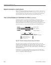
Figure D–7: Dielectric Constant and Velocity Factor, Short Distance
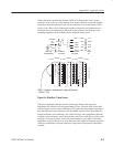
The round trip time should be located on the sliding scale that is above the
INCHES and CENTIMETERS scale. Place the point on the sliding scale next to
a point on one of the stationary scales that corresponds to the value of the
dielectric constant or velocity factor. Then read the distance on the INCHES and
CENTIMETERS scale.
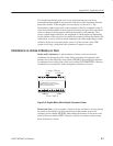
If the distance to or between faults is known and you want to find the time or
velocity factor, set the distance under the appropriate arrow first, then read the
answer on the ROUND TRIP TIME scales.


