Appendix B: Operator Performance Checks
B–4
1502C MTDR User Manual
O
N
ac 1.360 ft
O
F
F
O
F
F
O
F
F
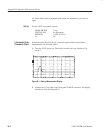
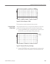
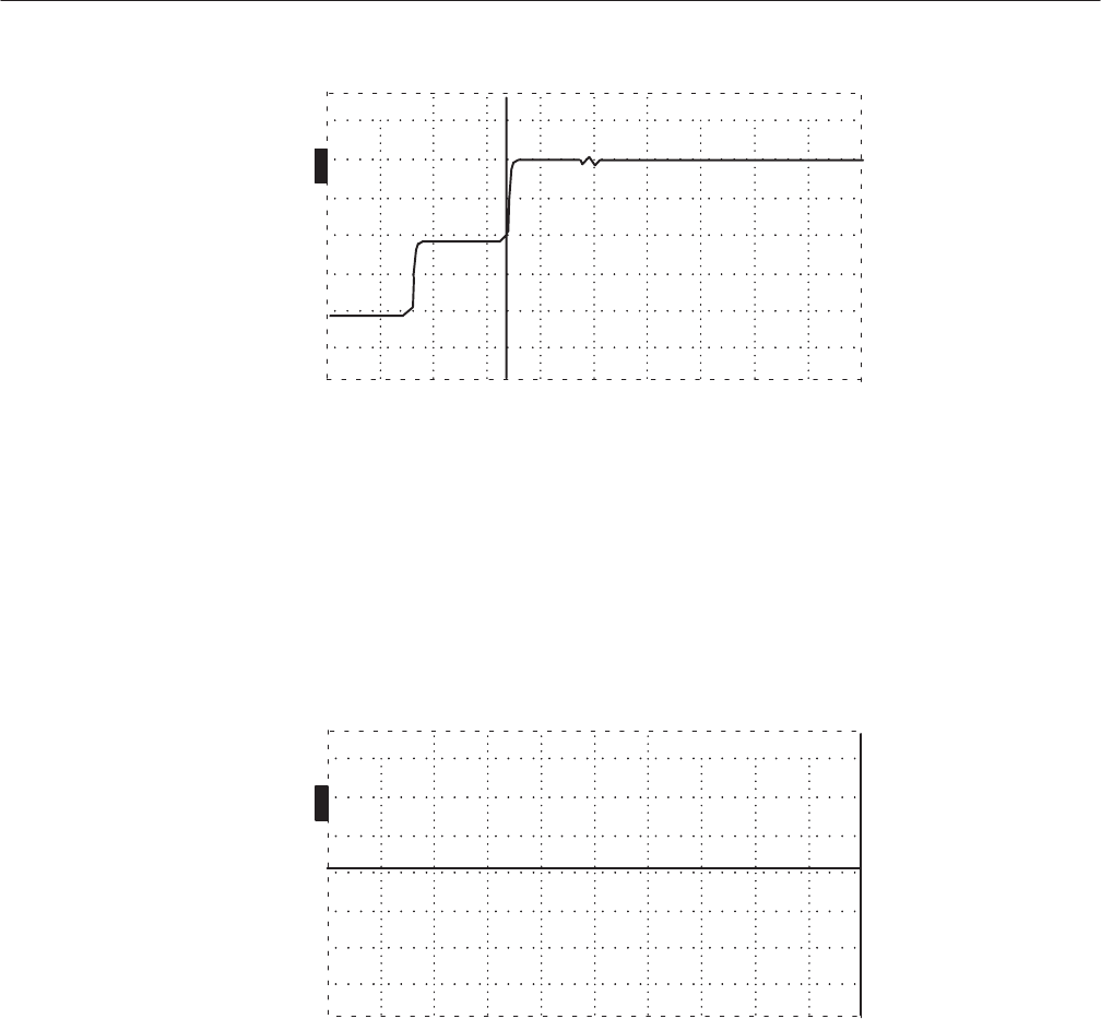
Figure B–4: Cursor at End of 3-foot Cable, Vp Set to .30
6. Remove the 3-foot cable and connect the 50 W terminator.
7. Change the DIST/DIV to 200 ft/div (50 m/div)
8. Turn the
n
o
POSITION control clockwise until the distance window shows a
distance greater than 2,000 feet (> 600 m). The waveform should be a flat
line from the pulse to this point.
O
F
F
O
F
F
O
F
F
O
N
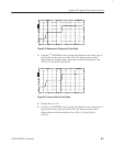
ac 2051.000 ft
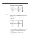
Figure B–5: Flat-Line Display Out to 50,0000+ Feet
9. Turn the
n
o
POSITION control counterclockwise until the distance window
shows a distance less than 10.000 feet (< 3.1 m).
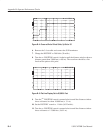
10. Set the DIST/DIV control to .1 ft/div (0.025 m/div).
11. Turn the
n
o
POSITION control counterclockwise until the distance window
shows a distance of –2.000 feet (–0.611 m).


