


Appendix D: Application Note
1502C MTDR User Manual
D–5
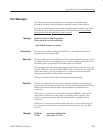
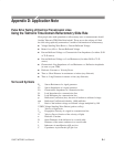
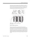
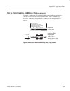
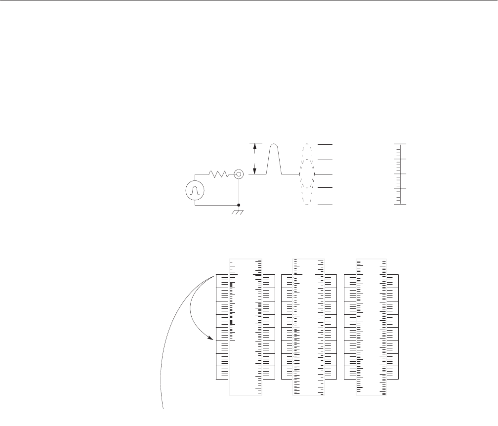
If the reflection is downward from the 50 W or 75 W reference level, set the
reference level to the top of the chosen scale. If the reflection is toward a higher
impedance than the reference level, set the reference level to the bottom of the
chosen scale. Then count off the right number of divisions and subdivisions to
locate the level corresponding to the peak of the reflection and read the corre-
sponding impedance levels (Ohms) on the adjacent sliding scale.
SOURCE
IMPULSE
GENERATOR
INCIDENT
VOLTAGE
REFLECTED
VOLTAGE
2E
PEAK
R
S
75 W
Z
O
75 W
LINE
–0dB =
–6dB =
–6dB =
–0dB =
+100%
+50%
0%
-50%
-100%
1 W
225 W
75 W
25 W
0 W
LOAD
R
L
% / DIV % / DIV % / DIV % / DIV
OHMS OHMS OHMS
20 10 5 2 1 .5
75 W SOURCE 75 W SOURCE 75 W SOURCE
75W
1dB =
E
PEAK
100
60
50
40
30
20
15
10
5
0
90
60
50
45
40
35
30
25
20
15
10
5
75W
80
70
65
60
55
50
45
40
35
30
70
65
60
55
76
74
73
72
70
69
68
67
66
65
64
63
71
75W
1
74
73
72
71
70
69
34
40
46
46
40
34
RETURN LOSS (–dB)
(20% / division, downward 5 major divisions)
–100% = 0 W
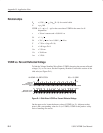
Figure D–4: Slide Rule 75 ohm Source
If the line impedance and the source resistance are known, the expected
amplitude of a reflection can be approximated. First, select the side of the slide
rule having the correct source impedance. For cables having a higher impedance
than the selected source resistance, put the sliding reference level even with the
bottom stationary scale markings. For cables having a lower impedance than the
selected source resistance, move the reference level even with the top of the scale
markings. For best accuracy, select the scale farthest to your right in which the
impedance level of interest is in view. Read from the adjacent stationary scale the
reflection coefficient or percent reflected voltage that corresponds to the Ohms
selected.