Appendix D: Application Note
1502C MTDR User Manual
D–3
NOTE. The relationship between % holds only when the loss is a single imped-
ance discontinuity with negligible capacitive or inductive components (e.g., a
75 W termination at the end of a 50 W cable). The VSWR must be essentially the
same for all sine-wave frequencies.
Return Loss (dB) vs. Percent Reflected Voltage
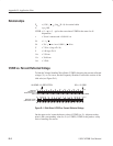
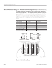
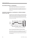
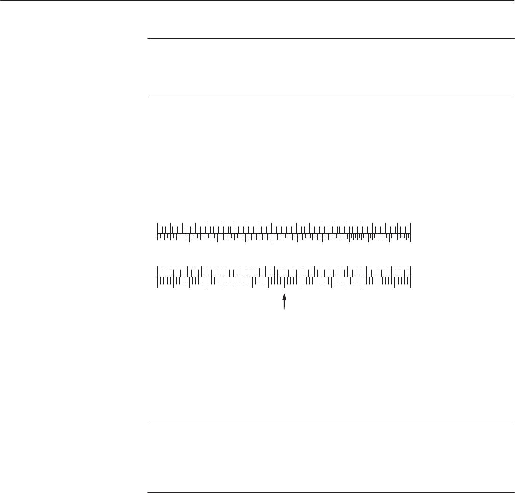
To find return loss in decibels, knowing the % (or vice versa), use the bottom
scale of the Frequency Domain Conversions section of the slide rule (see Figure
D–2).
0 2 4 6 81012141618 20 %
1.00 1.05 1.10 1.15 1.20 1.25 1.30 1.35 1.40 1.45 1.50 VWSR
80 75 70 65 60 55 50 45 40 35 30 25 20 15 10 5 0
.01 .02.03 .05 .10 .2 .3 .5 .7 1.0 2 3 5 7 10 20 50 100 %30
SINGLE
RESISTIVE
DISCONTINUITY
ONLY
RETURN LOSS
(IMPULSE ONLY)
1% REFLECTION = 40 dB RETURN LOSS
Figure D–2: Slide Rule of Return Loss vs. Percent Reflected Voltage
Locate the known value of % or the known dB return loss, then locate the value
of the corresponding expression on the adjacent scale.
NOTE. Only the impulse mode of Time-Domain Reflectometry can be accurately
expressed in terms of return loss.
A narrow impulse will be attenuated by losses in the cable and reflections will be
attenuated likewise.
As with measurements on VSWR, there is only a simple mathematical relation-
ship between reflection measurements using sine waves and reflection measure-
ments using pulses when one resistive discontinuity is the whole cause for the
sizable reflections.


