


Appendix D: Application Note
D–4
1502C MTDR User Manual
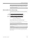
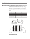
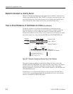
Percent Reflected Voltage vs. Characteristic Line Impedance (50 or 75 ohm Source)
To find the characteristic impedance of a line, or section of a line, knowing the
reflection coefficient or the %, you should first know the impedance of the pulse
generator. It should be as close as possible to the nominal impedance of the line
and should be connected to the line through a length of cable having the same
impedance as the source. Select the side of the slide rule that corresponds to the
source resistance (R
S
) of the generator used, then select the longest scale as
follows:
Size of Reflection % / division r / division
100% to 80% (1r to 0.8r) 20 .20
80% to 40% (0.8r to 0.4r) 10 .10
40% to 16% (0.4r to 0.16r) 5 .05
16% to 8% (0.16r to 0.08r) 2 .02
8% to 4% (0.08r to 0.04r) 1 .01
4% or less (< 0.04 r) 0.5 .005
+1r = ∞ W +.03r = 53.1W
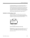
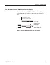
SOURCE
STEP
GENERATOR
INCIDENT
VOLTAGE
REFLECTED
VOLTAGE
D2E
R
S
50 W
Z
O
50 W
LINE
DE
+1r =
+0.5r=
0r =
-0.5r=
-1r =
+100%
+50%
0%
-50%
-100%
1 W
150 W
50 W
16.7 W
0 W
LOAD
R
L
r = REFLECTION COEFFICIENT
r / DIV r / DIV r / DIV r / DIV
OHMS OHMS OHMS
.20 .10 .05 .02 .01 .005
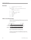
50 W SOURCE 50 W SOURCE 50 W SOURCE
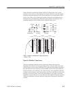
The risetime or amplitude of received reflections may be signi-
ficantly degraded or attenuated by two-way losses of the line .
1r = 100%
1
150
50W 50W 50W
1000
500
300
200
100
70
40
1000
600
400
300
200
100
90
80
70
60
45
40
120
100
90
80
70
60
70
68
66
64
62
60
58
56
54
52
49
48
59
58
57
56
55
54
53
52
51
51
52
53
54
Figure D–3: Slide Rule 50 ohm Source