


Appendix B: Operator Performance Checks
1502C MTDR User Manual
B–9
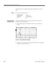
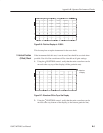
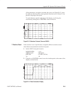
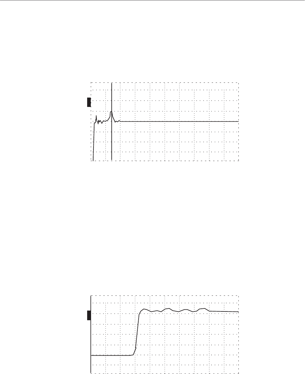
All the aberrations, except the one under the cursor (see Figure B–12), must
be within one division of the center graticule line from out to 10 feet (3.5 m)
past the rising edge of the pulse.
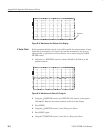
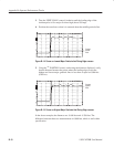
To verify distances past the right edge of the display, scroll along the
waveform by turning the
n
o
POSITION control clockwise.
O
F
F
O
F
F
O
F
F
O
N
ac 0.000 ft
Figure B–12: Waveform Centered, Cursor at 0.000 ft
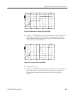
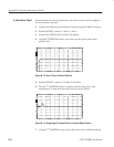
If the risetime is out of specification, it might be difficult to make accurate
short-distance measurements near the front panel.
1. Set the 1502C front-panel controls:
NOISE FILTER 1 avg
VERT SCALE 500 mr/div
DIST/DIV 0.2 ft/div (0.05 m)
Vp .99
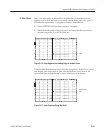
2. Using the
n
o
POSITION control, move the incident pulse to the center of the
display as shown below.
O
F
F
O
F
F
O
F
F
O
N
ac –1.432 ft
Figure B–13: Pulse Centered on Display
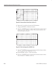
7. Risetime Check