Appendix D: Application Note
D–6
1502C MTDR User Manual
Percent Reflected Voltage vs. Load Resistance
To find the terminating load resistance (R
L
) of a line, knowing the percent
reflected voltage or reflection coefficient, use the preceding instructions.
If the load resistance is known, the previous procedures can be used to approxi-
mate the size of the return reflection. An error might be introduced if the
impedance of the connecting cable does not match the source resistance of the
pulse generator.
Characteristic Line Impedance or Load Resistance vs. Reflection Amplitude
(as seen on your TDR)
Line Impedance (Z
O
) or Load Resistance (R
L
) can be derived directly from the
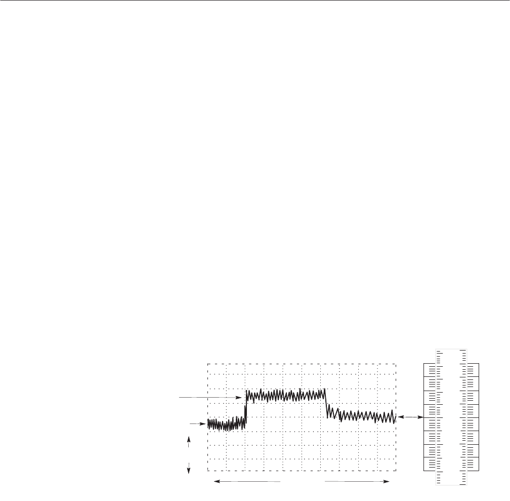
amplitude of a reflection displayed on a TDR display. The displayed reflection
should be positioned vertically to a known 50 W reference level. For a reference
level, use either a section of line of known impedance ahead of the line under
test/load, or use a termination of known resistance at the end of the line. The
slide rule can then be used by selecting the side with the same source resistance
and the same scale as the TDR.
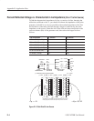
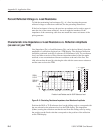
RG8/U
51.5 W
RG213/U
49.5 W
.01r/div
2 ns / div
Precision Load Resistor used for 50 W Reference Level
.01 .00
5
50 W SOURCE
50W
55
54
53
52
51
51
52
49
48
49
48
47
46
r / DIV
OHMS
Figure D–5: Calculating Resistance/Impedance from Waveform Amplitude
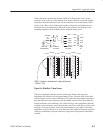
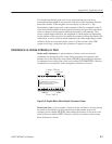
Position the 50 W or 75 W reference level on the sliding scale to correspond with
the one selected as the reference level on the TDR display. The impedance
(Ohms) causing the reflection can then be read from the sliding scale by noting
the position on the fixed scale that corresponds to the position of the reflection
on the TDR display.


