Appendix B: Operator Performance Checks
B–8
1502C MTDR User Manual
If the aberrations are out of specification, the ohms-at-cursor function might be
less accurate than specified.
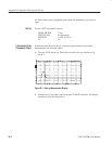
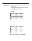
1. Connect the 50 W precision terminator to the front-panel CABLE connector.
2. Set the DIST/DIV control to 5 ft/div (1 m/div).
3. Increase the VERT SCALE control to 50 mr/div.
4. Using the
n
o
POSITION control, move the top of the pulse to the center
graticule line.
O
F
F
O
F
F
O
F
F
O
N
ac –1.872 ft
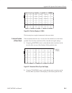
Figure B–10: Top of Pulse on Center Graticule
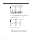
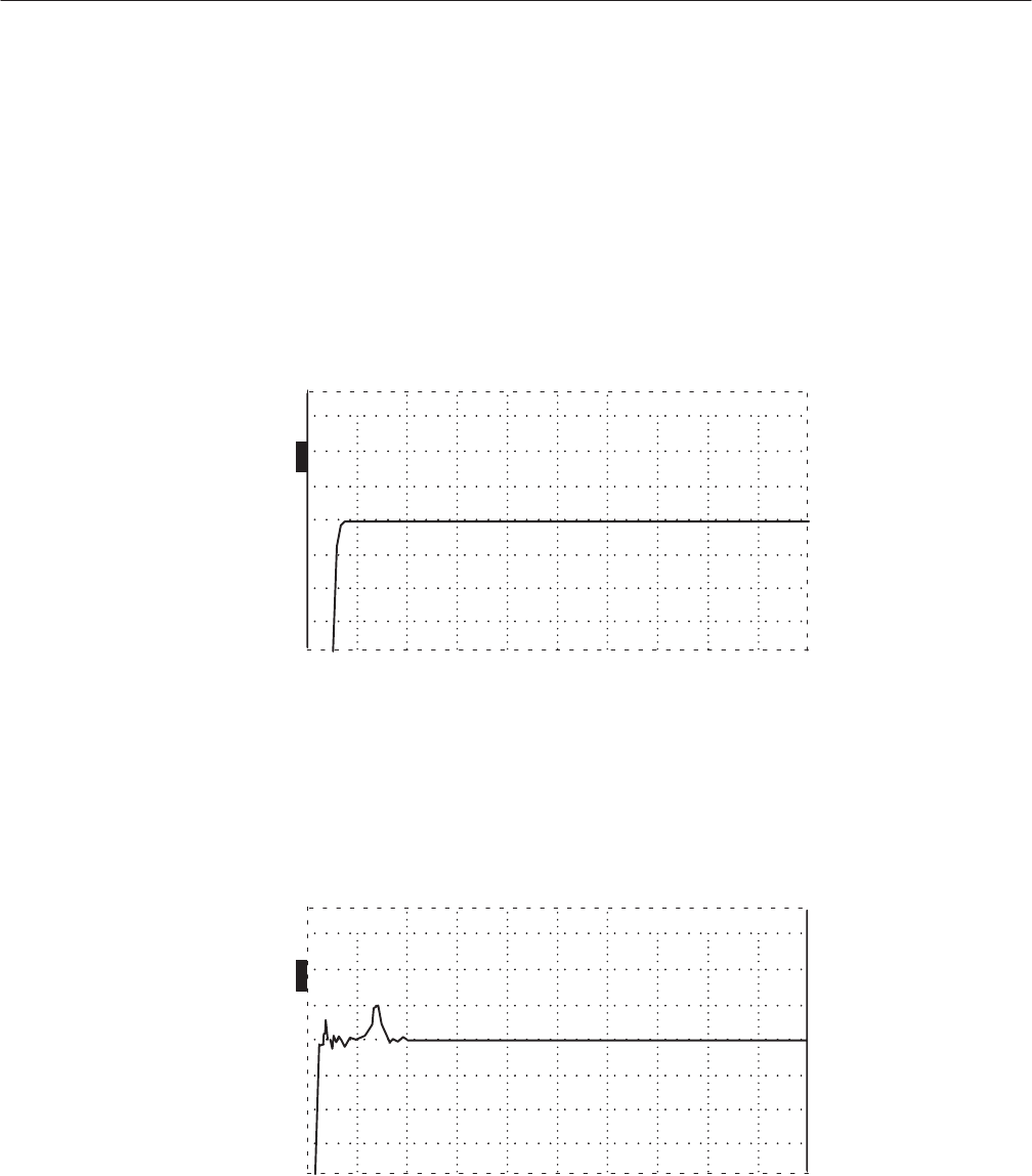
5. Set the DIST/DIV control to 0.2 ft/div (0.05 m/div).
6. Turn the
n
o
POSITION control clockwise until the rising edge of the
incident pulse is in the left-most major division on the display.
O
F
F
O
F
F
O
F
F
O
N
ac 1.744 ft
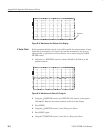
Figure B–11: Rising Edge of Incident Pulse in Left-most Major Division
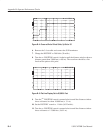
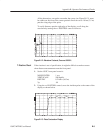
7. Using the
n
o
POSITION control, move the cursor back to 0.000 ft (0.00 m).
6. Aberrations Check


