


20 © 2007 Schneider Electric. All rights reserved.
Step 4: Wire the Communications
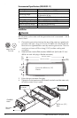
ION8800 meters are equipped with one standard optical port. Other
communications ports are available as options.
The Communications module cover plate (found on the back of the meter)
should never be removed unless a communications module is installed in its
place.
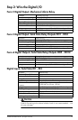
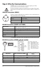
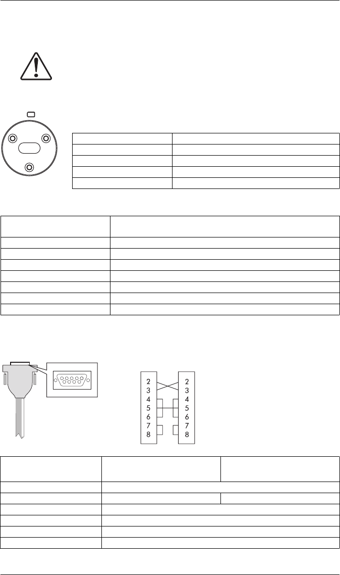
Infrared Connections (COM1)
Connect an optical probe cable (not included) to communicate between the
meter optical port and a PC serial port.
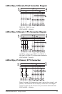
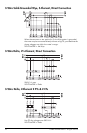
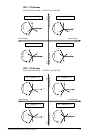
RS-485 Connections (COM2 and COM3)
* Use optional Common wire for improved communications performance.
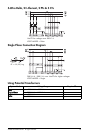
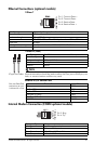
RS-232 Connections (COM3 optional module)
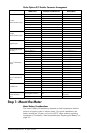
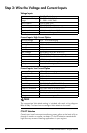
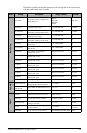
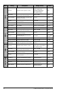
Interface IEC 1107 optical port
Location Front of meter
Data Rate 1,200 – 19,200 bps
Isolation Optical
Duplex Half
Ports Available
COM2: optional module or Essailec
COM3: optional module only
Connectors Captured-wire (+, –, Common*, Shield)
Wire Shielded 2 or 3-conductor RS-485 cable
Maximum Cable Length 1219 m (4,000 ft) total for entire bus
Data Rate 300 – 57,600 bps
Maximum Devices (per bus) 32
Isolation Optical
Duplex Half
51
96
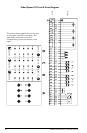
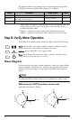
Null modem cable pinout
Pin 3 - Transmit Data - Pin 2
Pin 2 - Receive Data - Pin 3
Pin 7 - Request to Send- Pin 8
Pin 8 - Clear to Send- Pin 7
Pin 5 - Signal Ground- Pin 5
Pin 6 - Data Set Ready- Pin 4
Pin 4 - Data Terminal Ready-
Pin 6
DTE
(computer)
DTE
(meter)
DB9 Null Modem
Wiring Diagram
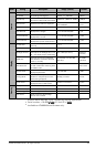
Specification Meter Connected to Computer
Meter Connected to External
Modem
Connector Type DB9 female end for mating with male connector on the meter
Wire Null modem RS-232 cable Straight-through RS-232 cable
Maximum Cable Length 15.2 m (50 ft)
Data Rate 300 – 115,200 bps
Isolation Optical
Duplex Full