


© 2007 Schneider Electric. All rights reserved. 15
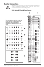
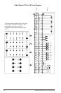
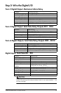
Step 2: Wire the Digital I/O
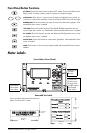
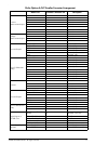
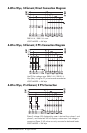
Form C Digital Output: Mechanical Alarm Relay
Form C Digital Output: Solid State Relay Outputs DO1 - DO4
Form A Digital Outputs: Solid State Relay Outputs DO5 - DO12
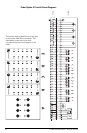
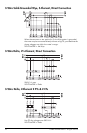
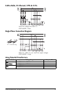
Digital Inputs: Solid State DI1 - DI3
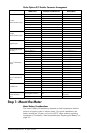
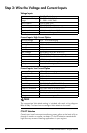
CAUTION
Field Hi-Pot testing to the above isolation levels is not recommended -- risk
of meter damage.
Contacts common, NO, NC
Max. Switching Voltage 250 VAC/125 VDC (internally limited to 300 V peak)
Max. Switching Current 1 A AC/0.1 A DC
Operate Time (max.) 8 ms
Release Time (max.) 4 ms
Isolation to Ground 2,000 VAC for 60 s (50 Hz)
Rating Installation category II (local), Pollution degree 2
Minimum Operations 5,000,000
Excitation External only
Contacts common, NO, NC
Max. Switching Voltage 250 VDC/ 210 VAC (internally limited to 350 V peak)
Max. Switching Current 100 mA AC/DC
Isolation to Ground 2,000 VAC for 60 s (50 Hz)
Rating Installation category II (local), Pollution degree 2
Excitation External only
Max. Switching Voltage 250 VDC/ 210 VAC (internally limited to 350 V peak)
Max. Switching Current 100 mA AC/DC
Isolation to Ground 2,000 VAC for 60 sec. (50 Hz)
Rating Installation category II (local), Pollution degree 2
Excitation External only
Minimum Pulse Width 1 ms
Maximum Pulse Rate 20 Hz
Timing Resolution 1 ms
Updated ½ cycle (does not affect timing resolution)
Isolation to Ground and to
Contacts
2,000 VAC for 60 sec. (50 Hz)
Rating Installation category II (local), Pollution degree 2
Hi-Voltage Range 75 - 280 VDC or VAC (RMS)
Lo-Voltage Range 15 - 75 VDC or VAC (RMS)
Hi-Voltage Input Impedance 100 kΩ
Lo-Voltage Input Impedance 20 kΩ