


16 © 2007 Schneider Electric. All rights reserved.
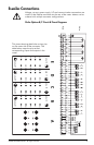
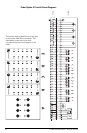
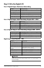
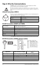
Step 3: Wire the Voltage and Current Inputs
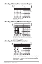
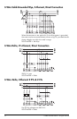
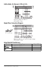
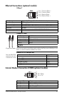
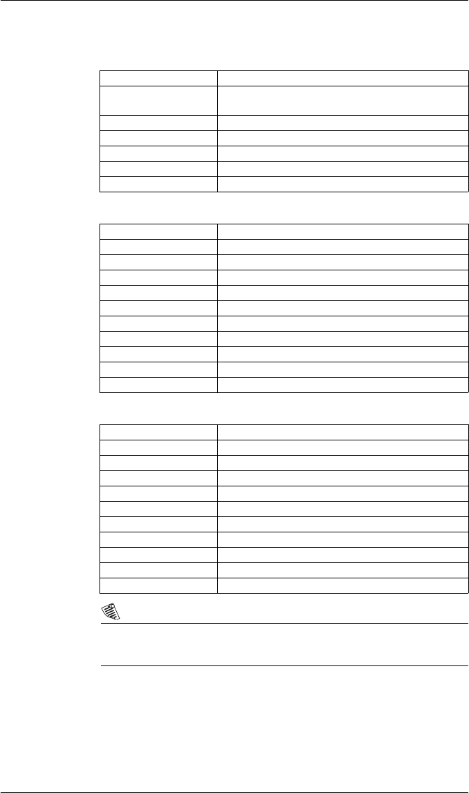
Voltage Inputs
Current Inputs: High Current Option
Current Inputs: Low Current Option
NOTE
The appropriate Volts Mode setting is included with each wiring diagram.
Refer to Step 7 to learn how to configure Volts Mode on the meter.
CT & PT Selection
Consult your local instrument transformer expert, either at the local utility or
through a vendor or supplier, to obtain CT and PT selection standards for
high accuracy revenue metering applications in your regions.
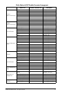
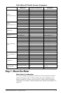
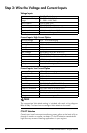
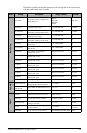
Inputs U1, U2, U3, Uref
Accuracy and Rating
Range
57 - 288 L-N VAC RMS
99 - 500 L-L VAC RMS
Fault Capture 1200 V peak (L-N)
Overload 1500 VAC RMS continuous
Dielectric Withstand 3320 VAC RMS at 50 Hz for 60 s
Input Impedance 5 MΩ/phase (phase - Vref)
Rating Measurement category IV
Accuracy Range 0.05 - 10 A autoranging
Rated Nominal 5 A
Starting Current 0.001 A RMS
Max. Current 10 A
Fault Capture 14 A peak
Max. Voltage 288 V RMS (Cat IV IEC 61010-1)
Overload 200 A RMS for 0.5 s, non-recurring
Dielectric Withstand 3320 VAC RMS at 50 Hz for 60 s
Burden 0.25 VA per phase (at 5 A)
Impedance 10 mΩ per phase
Rating Measurement category IV
Accuracy Range 0.01 - 6 A autoranging
Rated Nominal 1 A and 2 A
Starting Current 0.001 A RMS
Max Current 10 A
Fault Capture 14 A peak
Max. Voltage 288 V RMS (Cat IV IEC 61010-1)
Overload 200 A RMS for 0.5 s, non-recurring
Dielectric Withstand 3320 VAC RMS at 50 Hz for 60 s
Burden 0.01 VA per phase (at 1 A)
Impedance 10 mΩ per phase
Rating Measurement category IV