10-4 CONTROL BOX CHECK, DISASSEMBLY, and REASSEMBLY
10-4-l CHECK
Check the wiring bp removing the control box from
the
frame and taking the panel B (rear panel) off,
10-4-2 DISASSEMBLY
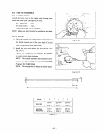
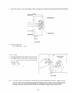
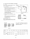
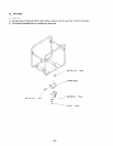
1) Remove the control box panel B (.rear panel) and the
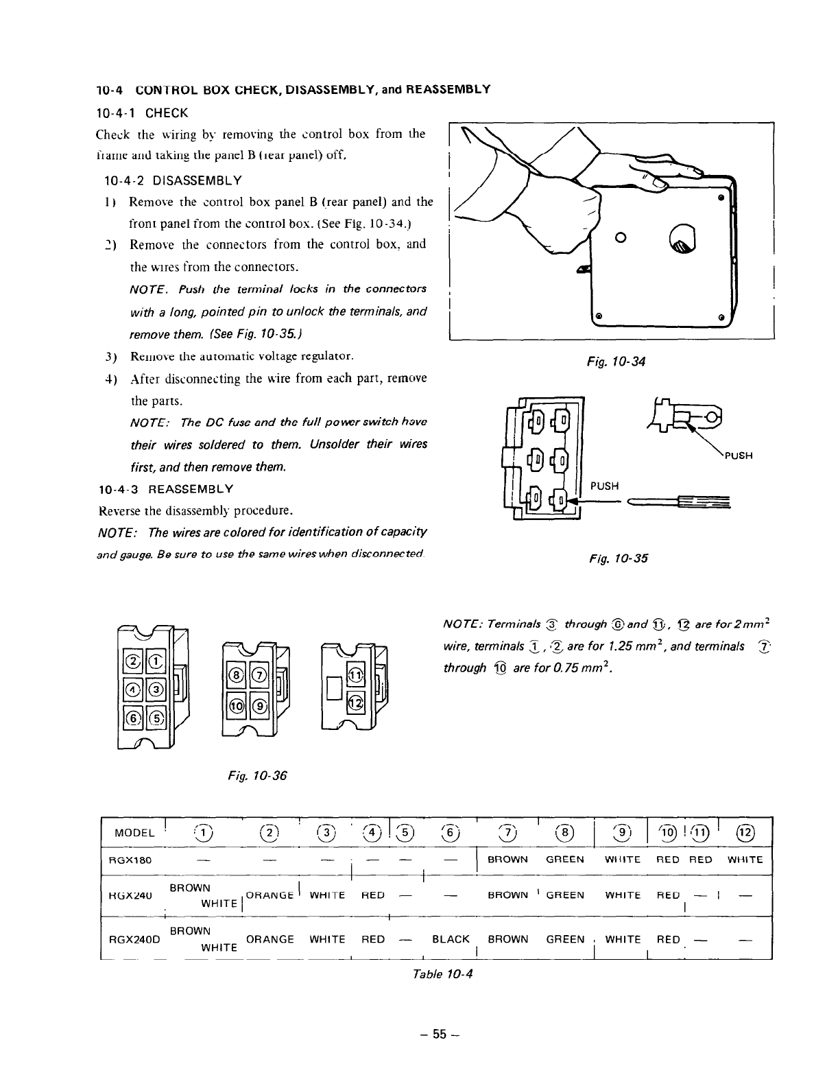
front panel from the control box. (See Fig. 10-34.)
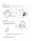
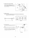
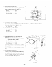
2) Remove the connectors from the control box, and
the wires from the connectors.
NOTE: Push the terminal locks in the connectors
with a long, pointed pin to unlock the terminals, and
remove them. (See Fig. 10-35.)
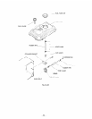
3) Remove the automatic voltage regulator.
4) *After disconnecting the wire from each part, remove
the parts.
NOTE:
The DC fuse and the full power switch have
their wires soldered to them. Unsolder their wires
first, and then remove them.
10-4-3 REASSEMBLY
Keverse the disassembly procedure.
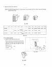
NOTE: The wires are colored for identification of capacity
and gauge. Be sure to use the same wires when disconnected.
Fig. lo-34
PUSH
9
PUSH
C
--I
Fig. lo-35
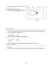
NOTE: Terminals 3 through ,$land j-j;. g are for2mm’
wire, terminals
i
m? are for 1.25 mm’, and terminals
L'd
z
through @ are for 0.75 mm’.
Fig. lo-36
I
MODEL
:@ ,T,
d
RGXl80
- -
-:- -
BROWN
GREEN WHITE
RED RED WHITE
I
i
BROWN
RGX240
WHITE 1
ORANGE
WHITE
RED - - BROWN
’ GREEN WHITE RED - I -
I
-
BROWN
RGX240D ORANGE WHITE
RED - BLACK BROWN
GREEN 8 WHITE
RED - -
WHITE
I
I
Table 10-4
- 55 -


