l
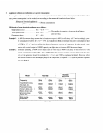
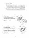
50Hz 11
OVi22OV.
12OVf24OV
I
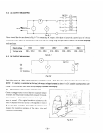
Wire color
RED , BLACK
I
WHITE ’
1.15Q
I “,“:y - $1
1.15x? !
l
60Hz
1 lou;22ou. 12oui24ou
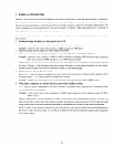
9-l-2 MEASURING INSULATION RESISTANCE
Refer to
8-4 MEASURING INSULATION RESISTANCE.
9-2 ROTOR ASSEMBLY
ROTOR
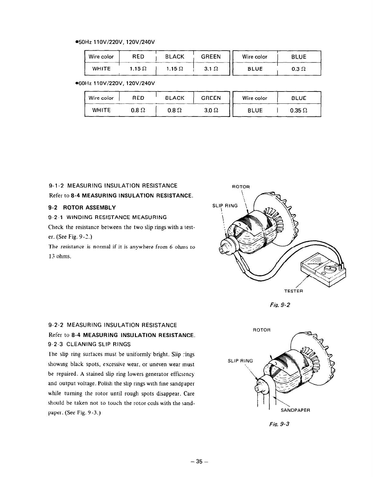
9-2-l WI-NDING RESISTANCE MEASURING
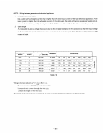
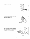
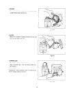
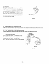
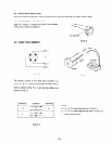
Check the resistance between the two slip rings with a test-
er. (See Fig. 9-2.)
The resistance is normal if it is an>vhere from 6 ohms to
13 ohms.
TESTER
Fig. 9-2
9-2-2 MEASURING INSULATION RESISTANCE
Refer to
8-4 MEASURING INSULATION RESISTANCE.
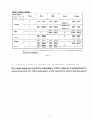
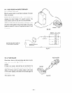
9-2-3 CLEANING SLIP RINGS
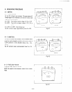
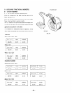
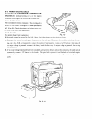
The slip ring surfaces must be uniformly bright. Slip :-ings
showing black spots. excessive wear, or uneven wear must
be repaired. A stained slip ring lowers generator effi;rency
and output voltage. Polish the slip rings with fine sandpaper
while turning the rotor until rough spots disappear. Care
should be taken not to touch the rotor ~011s with the sand-
paper. (See Fig. 9 -3 .)
ROTOR
f=-%
SLIP RING
-\
. . . .
\
Fig. 9-3
-35-


