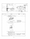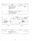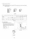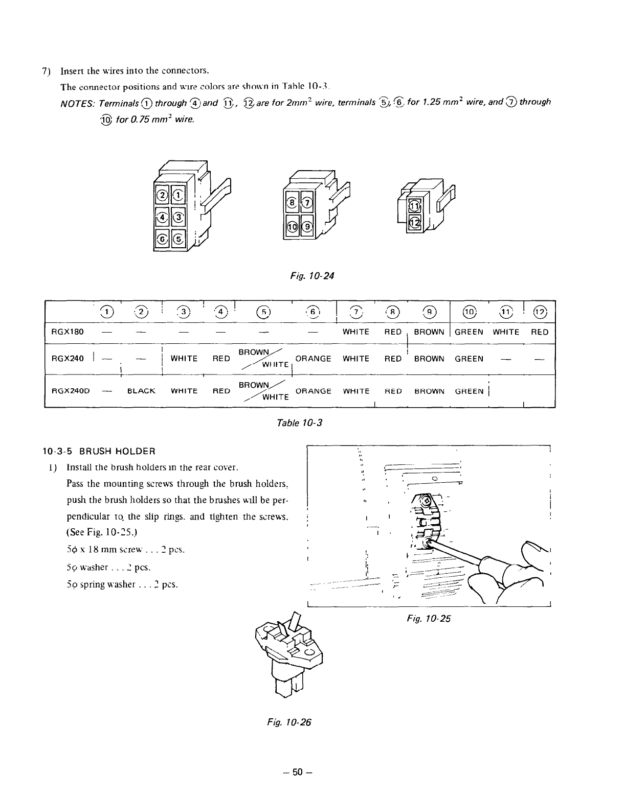
7j Insert the wires into the connectors.
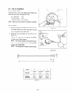
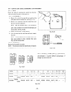
The connrctor positions and wtr2 colors are shown in Table 10-J.
NOTES: Terminals 3 through ‘z; and cj,
@are for 2mm’ wire, terminals ‘5,s. for 1.25 mm’ wire, and .z~ through
c$ij for 0.75 mm’ wire.
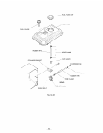
Fig. lo-24
n
I
I
3
::z / 12; ’ .zj !
RGX180 - -
-
WHITE RED i BROWN GREEN WHITE
RED
I
RGX240 1 - -
I
I
i WHITE
RED
ORANGE
WHITE
RED BROWN GREEN - -
I
1
RGX240D -
BLACK
WHITE RED
WHITE RED
BROWN GREEN 1
I
I
Table 70-3
10-3-5 BRUSH hOLDER
:.
I
I.
II
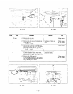
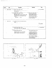
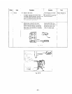
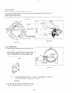
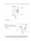
1) Install the brtish holders in the rear cover.
.I
II
,
Pass the mounting screws through ths brush holders,
,I I
., c
,I ’
I
push the brush holders SO that the brushes w-111 be prr-
/
I
‘1 I
I
pendicular to.
the
slip rings. and tighten
ths
screws.
j
I
I
-
(Se2 Fig. lo-~5.j
I
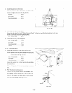
-Qslgmmscrew...?pcs.
50 washzr . 2 PCS.
5~ spring washer 2 pcs.
Fig. lo-25
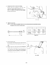
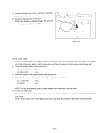
Fig. lo-26
- 50 -


