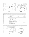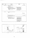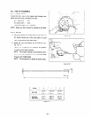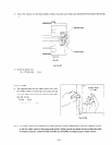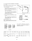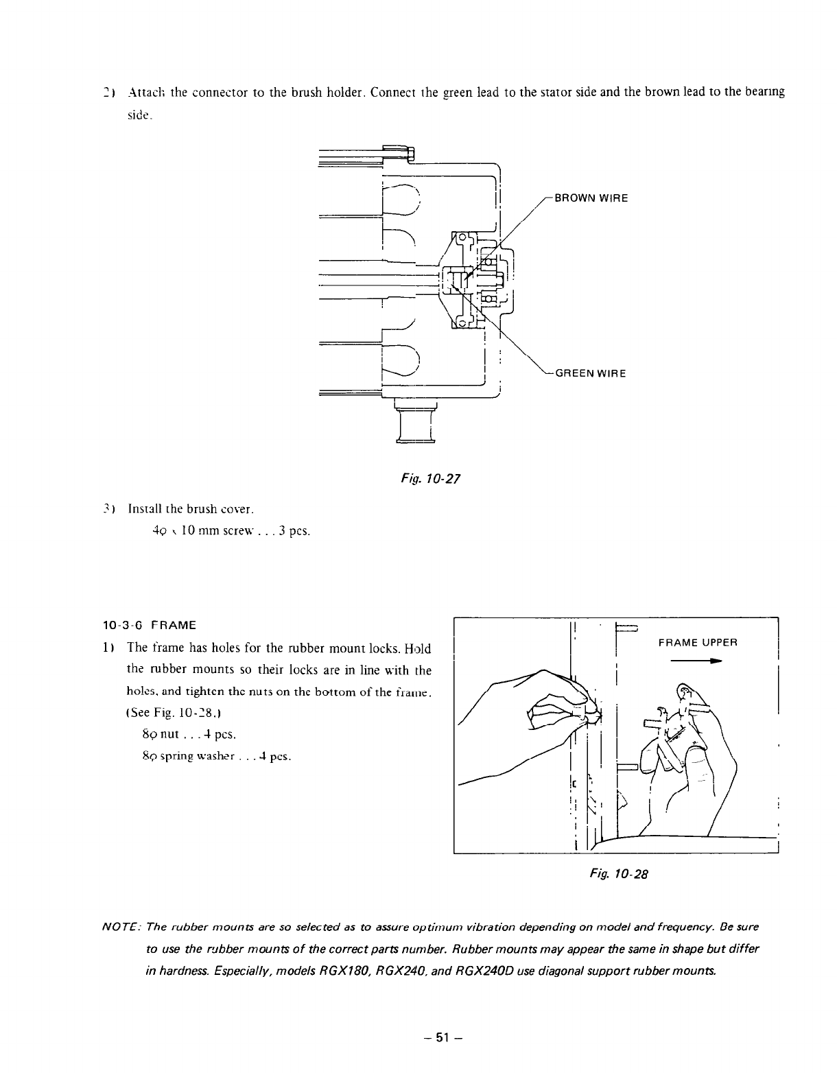
2 I Attach the connector to the brush holder. Connect the green lead to the stator side and the brown lead to the bearing
side.
Ficr. 7 O-27
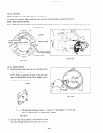
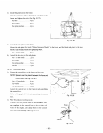
3) Install the brush cover.
49 x 10 mm screw . . 3 pcs.
10-3-6 FRAME
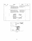
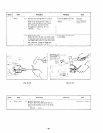
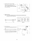
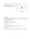
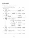
1 I The frame has holes for the rubber mount locks. Hold
the rubber mounts so their locks are in line with the
ho!es. and tighten the nuts on the bottom of the frame.
(See Fig. 10-28.)
8~ nut . .4 pcs.
8Q
spring washer -! pcs.
GREEN WIRE
FRAME UPPER
Fig. 10-28
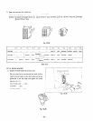
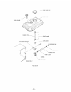
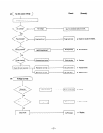
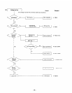
NOTE: The rubber mounts are so selected as to assure optimum vibration depending on model and frequency. Be sure
to use the rgbber mounts of the correct parts number. Rubber mounts may appear the same in shape but differ
in hardness. Especially, models RGX780, RGX240. and RGX240D use diagonal support rubber mounts.
-51 -


