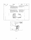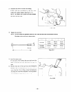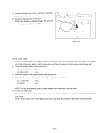
3) Connect the connectors to the control box. And push
the connectors into the control box.
4j
Install the bushing on the control box.
NOTE: No clearance is allowed between the grommet
and bushing. (See Fig. 10-32.)
I-
‘1 -
Fig. lo-32
10-3-8 FUEL TANK
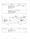
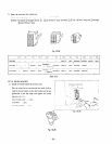
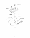
1) Connect the rubber pipe to the engine carburetor and fasten it with the hose clamp. Attach the banjo to the opposite
end of the rubber pipe. tighten it with the hose clam?. and fasten the pipe to the fuel strainer with the banjo bolt.
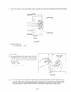
3 I Attach the strainer bracket to the control box.
lox 10mmbolts . . . . .2pcs.
4~ spring washer . . _ . .2 pss.
3) Fasten the strainer to the strainer bracket with the joint nuts.
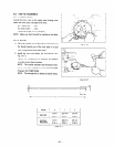
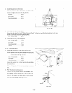
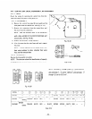
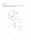
4) Mount the fuel tank on the side plates with rubber washers between the t\vo.
6d x 20 mm bolts _ . . _ .4 PCS.
69 washers . . . . . . . .4 PCS.
60 spring washers . _ . 1 PCS.
NOTE: For easy tank assembly, glue the rubber washers around the holes in the side plates.
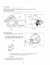
5) Connect the rubber pipe
First. fit the hose clamps on the rubber pipe. connect the strainer and fuel tank. then fasten the rubber pipe wth the
hose clamps.
NOTE: Apply a drop of oil to the rubber pipe so that it may easily be connected to the strainer and the fuel tank.
- 53 -


