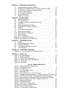
SECTION 7 − SEQUENCE OF OPERATION
7-1. Shielded Metal Arc Welding (SMAW) 19. . . . . . . . . . . . . . . . . . . . . . . . . .
7-2. Gas Metal Arc (GMAW) And Flux Cored Arc Welding (FCAW) 19. . . .
7-3. Air Carbon Arc Cutting And Gouging (CAC-A) 20. . . . . . . . . . . . . . . . . . .
7-4. Auxiliary Power Operation 20. . . . . . . . . . . . . . . . . . . . . . . . . . . . . . . . . . . .
7-5. Air Compressor Operation 20. . . . . . . . . . . . . . . . . . . . . . . . . . . . . . . . . . . .
7-6. Starting The Engine 20. . . . . . . . . . . . . . . . . . . . . . . . . . . . . . . . . . . . . . . . .
7-7. Stopping The Engine 21. . . . . . . . . . . . . . . . . . . . . . . . . . . . . . . . . . . . . . . .
SECTION 8 − MAINTENANCE
8-1. Routine Maintenance 23. . . . . . . . . . . . . . . . . . . . . . . . . . . . . . . . . . . . . . . .
8-2. Air Cleaner Service 25. . . . . . . . . . . . . . . . . . . . . . . . . . . . . . . . . . . . . . . . . .
8-3. Fuel/Water Separator And Sludge Drain Plug 26. . . . . . . . . . . . . . . . . . .
8-4. Fuel Filter 26. . . . . . . . . . . . . . . . . . . . . . . . . . . . . . . . . . . . . . . . . . . . . . . . . .
8-5. Battery Replacement Procedure 26. . . . . . . . . . . . . . . . . . . . . . . . . . . . . .
8-6. Maintenance-Free Battery Charging 27. . . . . . . . . . . . . . . . . . . . . . . . . . .
8-7. Governor 27. . . . . . . . . . . . . . . . . . . . . . . . . . . . . . . . . . . . . . . . . . . . . . . . . .
8-8. Engine Speed Adjustments 27. . . . . . . . . . . . . . . . . . . . . . . . . . . . . . . . . . .
8-9. Brushes And Slip Rings 28. . . . . . . . . . . . . . . . . . . . . . . . . . . . . . . . . . . . . .
8-10. Ether Starting Aid (Optional) 28. . . . . . . . . . . . . . . . . . . . . . . . . . . . . . . . . .
8-11. Spark Arrestor 28. . . . . . . . . . . . . . . . . . . . . . . . . . . . . . . . . . . . . . . . . . . . . .
8-12. Run-In Procedure 29. . . . . . . . . . . . . . . . . . . . . . . . . . . . . . . . . . . . . . . . . . .
Diagram 8-1. Load Bank Connections 30. . . . . . . . . . . . . . . . . . . . . . . . . . . . . . . .
Diagram 8-2. Resistance Grid Connections 31. . . . . . . . . . . . . . . . . . . . . . . . . . .
SECTION 9 − TROUBLESHOOTING
9-1. General 31. . . . . . . . . . . . . . . . . . . . . . . . . . . . . . . . . . . . . . . . . . . . . . . . . . . .
9-2. Booster Battery Jump Starting 31. . . . . . . . . . . . . . . . . . . . . . . . . . . . . . . .
9-3. Overload Protection 32. . . . . . . . . . . . . . . . . . . . . . . . . . . . . . . . . . . . . . . . .
9-4. Circuit Board Handling Precautions 32. . . . . . . . . . . . . . . . . . . . . . . . . . . .
9-5. Troubleshooting 33. . . . . . . . . . . . . . . . . . . . . . . . . . . . . . . . . . . . . . . . . . . . .
SECTION 10 − ELECTRICAL DIAGRAMS
Diagram 10-1. Circuit Diagram For Welding Generator 36. . . . . . . . . . . . . . . . . .
SECTION 11 − PARTS LIST
Figure 11-1A. Main Assembly 38. . . . . . . . . . . . . . . . . . . . . . . . . . . . . . . . . . . . . . .
Figure 11-1B. Main Assembly 42. . . . . . . . . . . . . . . . . . . . . . . . . . . . . . . . . . . . . . .
Figure 11-2. Panel, Front w/Components 44. . . . . . . . . . . . . . . . . . . . . . . . . . . . .
Figure 11-3. Panel, Lower Front w/Components 46. . . . . . . . . . . . . . . . . . . . . . .
Figure 11-4. Control Box 48. . . . . . . . . . . . . . . . . . . . . . . . . . . . . . . . . . . . . . . . . . . .
Figure 11-5. Generator 49. . . . . . . . . . . . . . . . . . . . . . . . . . . . . . . . . . . . . . . . . . . . .
LIST OF TABLES AND CHARTS
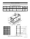
Table 3-1. Welding Generator Specifications 7. . . . . . . . . . . . . . . . . . . . . . . . . .
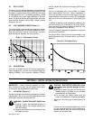
Chart 3-1. Volt-Ampere Curves 8. . . . . . . . . . . . . . . . . . . . . . . . . . . . . . . . . . . . . .
Chart 3-2. Air Output Curve 8. . . . . . . . . . . . . . . . . . . . . . . . . . . . . . . . . . . . . . . . .
Chart 4-1. Fuel Consumption Curve 10. . . . . . . . . . . . . . . . . . . . . . . . . . . . . . . . . .
Table 4-1. Weld Cable Size 11. . . . . . . . . . . . . . . . . . . . . . . . . . . . . . . . . . . . . . . . .
Chart 5-1. AC Power Curve For 120 Volt Terminals 15. . . . . . . . . . . . . . . . . . . . .
Table 7-1. Suggested Electrode Diameter For Amperage Range (CAC-A Only) 20
Table 7-2. Flow Of Free Air (CFM) Through Orifices Of Various Diameters 21
Table 7-3. Approximate Air Consumption (Cubic Feet) Required To Operate
Various Pneumatic Equipment At Pressure Range 70-90 P.S.I.G. 22. . . . . . . .
Table 8-1. Maintenance Schedule 23. . . . . . . . . . . . . . . . . . . . . . . . . . . . . . . . . . . .
Table 8-2. Air Cleaner Service 25. . . . . . . . . . . . . . . . . . . . . . . . . . . . . . . . . . . . . . .
Table 9-1. Weld/Power Troubleshooting 33. . . . . . . . . . . . . . . . . . . . . . . . . . . . . . .
Table 9-2. Auxiliary Power Troubleshooting 34. . . . . . . . . . . . . . . . . . . . . . . . . . . .
Table 9-3. Engine Troubleshooting 34. . . . . . . . . . . . . . . . . . . . . . . . . . . . . . . . . . .
Table 9-4. Air Compressor Troubleshooting 34. . . . . . . . . . . . . . . . . . . . . . . . . . .


