


OM-166 941 Page 17
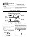
A. START Position
Rotating the switch to the START position starts the en-
gine. Release the switch as soon as the engine starts,
and the switch automatically returns to the RUN posi-
tion.
B. RUN Position
RUN
When the Engine Control switch is in the RUN position,
engine speed remains at governed weld/power speed
(1860 rpm).
C. OFF Position
Rotating the Engine Control switch to the OFF position
disconnects battery voltage, thereby shutting down the
engine.
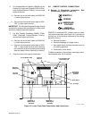
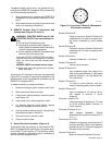
6-4. REMOTE AMPERAGE & VOLTAGE CON-
TROL SWITCH (Figure 6-1)
A/V
REMOTE
PANEL
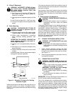
WARNING: ELECTRIC SHOCK can kill.
• Do not touch live electrical parts.
• Do not touch the output terminals when the
contactor is energized
• Do not touch welding wire or electrode and
work clamp at same time.
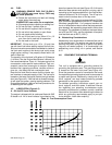
If remote amperage or voltage control is desired, make
connections to the REMOTE 9 receptacle terminal strip
according to Section 4-8, and place the AMPERAGE &
VOLTAGE switch in the REMOTE position. When a Re-
mote Amperage or Voltage Control is being used, the re-
mote control functions as a fine amperage or voltage ad-
justment for the AMPERAGE & VOLTAGE ADJUST-
MENT control on the welding generator. For example, if
the AMPERAGE & VOLTAGE ADJUSTMENT control
on the welding generator is set at midrange, the Remote
Amperage or Voltage Control will provide (from mini-
mum to maximum adjustment) fine amperage or voltage
adjustment of one half of the welding generator output
for the range selected. For complete remote control of
the output, rotate the AMPERAGE & VOLTAGE AD-
JUSTMENT control to the maximum position.
If remote amperage or voltage is not desired, place the
AMPERAGE & VOLTAGE switch in the PANEL posi-
tion. Only the AMPERAGE & VOLTAGE ADJUST-
MENT control will adjust output.
6-5. OUTPUT(CONTACTOR) SWITCH (Figure
6-1)
REMOTE
OUTPUT
(CONTACTOR)
ON
WARNING: ELECTRIC SHOCK can kill.
• Do not touch live electrical parts.
• Do not touch the output terminals when the
contactor is energized.
• Do not touch welding wire or electrode and
work clamp at same time.
When the OUTPUT/CONTACTOR switch is in
the ON position, open-circuit voltage is present
at the weld output terminals for as long as the
engine is running.
If the OUTPUT(CONTACTOR) switch is in the ON posi-
tion, open-circuit voltage will be present at the output
terminals whenever the engine is running.
If remote contactor control by means of a wire feeder or
remote device is desired, make connections to the RE-
MOTE 9 receptacle or terminal strip 3T according to
Section 4-8, and place the OUTPUT(CONTACTOR)
switch in the REMOTE position. Open-circuit voltage is
present at the weld output terminals whenever the gun
switch or remote device is closed.
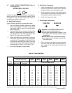
6-6. SERVICE ENGINE AIR CLEANER LIGHT
(Figure 6-1)
This unit is equipped with an engine air cleaner. When
the SERVICE ENGINE AIR CLEANER light PL1 comes
on, the air cleaner requires servicing (see Section 8-2).
6-7. CHECK ALTERNATOR (Figure 6-1)
The CHECK ALTERNATOR light PL3 comes on if the al-
ternator requires servicing. If the light comes on, check
for loose or broken engine belt.
6-8. HOUR METER (Figure 6-1)
This unit is equipped with an hour meter. The meter, la-
beled ENGINE HOURS, registers the total hours of en-
gine operation. This information is useful for routine
maintenance on the engine.