


OM-166 941 Page 18
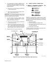
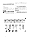
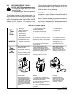
6-9. FUEL GAUGE (Figure 6-1)
FUEL
The FUEL Gauge indicates the level of fuel remaining in
the fuel tank. The unit is equipped with a 30 gallon (114
L) fuel tank.
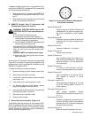
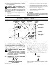
6-10. MAGNETIC SHUTDOWN SWITCH
An internal switch automatically shuts down the engine
if oil pressure drops to an unsafe level or oil temperature
becomes too high.
The switch assembly is located directly behind the up-
per front panel access door, in the upper left corner. The
switch is protected by a fuse located on the bottom of the
switch assembly. Should this fuse open, the engine
would not start. See Section 9-3 for fuse replacement
procedure.
6-11. OIL TEMPERATURE GAUGE/SWITCH (Fig-
ure 6-1)
The OIL TEMPERATURE gauge/switch registers the
temperature of the oil in the lubricating system. If the oil
temperature rises to a level that may cause engine dam-
age (factory set at 265°F, 130°C), switch closes and
magnetic shutdown switch stops the engine (see Sec-
tion 6-10).
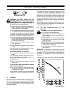
6-12. OIL PRESSURE GAUGE/SWITCH (Figure
6-1)
The OIL PRESSURE gauge/switch registers the lubri-
cating system pressure in pounds per square inch (psi).
The pressure registered by the gauge should remain
constant for a given engine speed. Should the pressure
fluctuate or drop, stop the engine, and do not operate
until the trouble has been corrected. If the oil pressure
drops to a level that may cause engine damage, switch
closes and magnetic shutdown switch stops the engine
(see Section 6-10). The shutdown oil pressure is factory
set at 30 psi (207 kPa). Normal operating pressure is ap-
proximately 50 psi (345 kPa).
6-13. BATTERY GAUGE (Figure 6-1)
+
BATTERY
The BATTERY voltmeter registers the alternator-
supplied output voltage to the battery. The meter should
always register 12-15 volts dc while the engine is run-
ning. If the voltage is outside this range, stop the engine,
and determine the cause. Do not operate the engine un-
til the trouble has been corrected.
6-14. METERS (Figure 6-1)
The meters are provided to monitor the welding opera-
tion; however, they are not intended for exact amperage
or voltage measurements. These meters are internally
connected to the output circuit.
The voltmeter indicates the voltage at the weld termi-
nals, but not necessarily the actual voltage at the weld-
ing arc (due to cable resistance, poor connections, etc.).
The ammeter indicates the amperage output of the unit.
6-15. BROKEN COOLING BELT SHUTDOWN
SWITCH
An internal switch automatically shuts down the engine
if the cooling belt breaks. The cooling belt is located on
the rear of the engine. If the engine shuts down, check
for broken cooling belt.
6-16. ETHER STARTING AID (Optional)
The cold weather starting components provide a means
of applying a premeasured portion of ether into the man-
ifold. The amount of ether supplied should be sufficient
to permit easy engine starting under cold weather condi-
tions.
Depressing ETHER STARTING AID switch for one sec-
ond while cranking the engine will provide the proper
amount of ether to the manifold. This control will function
only while cranking the engine.
CAUTION: ETHER INJECTION WHILE EN-
GINE IS RUNNING can cause engine dam-
age.
• Do not actuate ETHER STARTING AID while
engine is running.
IMPORTANT: Ether is sprayed into the engine when
this switch is released. Depressing the switch does not
spray the ether into the engine but rather fills the valve
chamber.