


OM-166 941 Page 11
4-7. WELD OUTPUT CONNECTIONS (Table 4-1
And Figure 4-2)
RATED WELD OUTPUT
To obtain full rated output from this unit, it is necessary to
select, prepare, and install proper weld cables. Failure
to comply in any of these areas may result in
unsatisfactory welding performance.
A. Weld Cable Selection
Use the following guidelines to select weld cables:
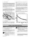
1. Use the shortest possible cables, and place
cables close together. Excessive cable lengths
may reduce output or cause unit overload due to
added resistance.
2. Use weld cable with an insulation voltage rating
equal to or greater than the maximum open-cir-
cuit voltage (ocv) of the welding generator (see
Table 3-1 for unit maximum ocv rating).
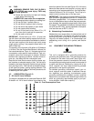
3. Select weld cable size according to maximum
weld output and total length of connecting cables
in weld circuit. For example, if a 25 foot (7.5 m)
wire feeder or electrode holder cable is used with
a 25 foot (7.5 m) work cable, select the cable size
recommended in Table 4-1 for 50 feet (15 m).
4. Do not use damaged or frayed cables.
B. Weld Cable Preparation
1. Install electrode holder to cable following man-
ufacturer’s instructions. Always use an insulated
electrode holder to ensure operator safety.
2. Install correct size lugs onto ends of both cables
for connecting to work clamp, electrode holder or
wire feeder, and weld output terminals.
3. Install work clamp onto cable.
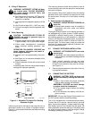
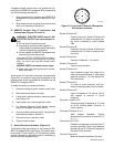
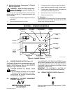
C. Weld Output Connections
POSITIVE NEGATIVE
+
−
WARNING: ELECTRIC SHOCK can kill.
• Do not touch live electrical parts.
• Stop engine, and disconnect negative (−) bat-
tery cable before making any weld output
connections.
MOVING PARTS can cause serious injury.
• Keep away from moving parts such as fans,
belts, and rotors.
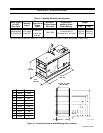
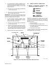
1. Open and secure the lower front panel access
door, and route weld cables through bracket on
front upright to the weld output terminals (see
Figure 4-2).
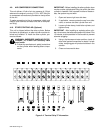
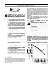
Table 4-1. Weld Cable Size*
Total Cable (Copper) Length In Weld Circuit Not Exceeding
100 ft (30 m) Or Less
150 ft
(45 m)
200 ft
(60 m)
250 ft
(70 m)
300 ft
(90 m)
350 ft
(105 m)
400 ft
(120 m)
Welding
Amperes
10 To 60%
Duty Cycle
60 Thru 100%
Duty Cycle
10 Thru 100% Duty Cycle
100 4 4 4 3 2 1 1/0 1/0
150 3 3 2 1 1/0 2/0 3/0 3/0
200 3 2 1 1/0 2/0 3/0 4/0 4/0
250 2 1 1/0 2/0 3/0 4/0 2-2/0 2-2/0
300 1 1/0 2/0 3/0 4/0 2-2/0 2-3/0 2-3/0
350 1/0 2/0 3/0 4/0 2-2/0 2-3/0 2-3/0 2-4/0
400 1/0 2/0 3/0 4/0 2-2/0 2-3/0 2-4/0 2-4/0
500 2/0 3/0 4/0 2-2/0 2-3/0 2-4/0 3-3/0 3-3/0
600 3/0 4/0 2-2/0 2-3/0 2-4/0 3-3/0 3-4/0 3-4/0
700 4/0 2-2/0 2-3/0 2-4/0 3-3/0 3-4/0 3-4/0 4-4/0
800 4/0 2-2/0 2-3/0 2-4/0 3-4/0 3-4/0 4-4/0 4-4/0
900 2-2/0 2-3/0 2-4/0 3-3/0 3-4/0 4-4/0 4-4/0
*Weld cable size (AWG) is based on either a 4 volts or less drop or a current density of at least 300 circular mils per ampere. S-0007-D