


OM-166 941 Page 27
8-6. MAINTENANCE-FREE BATTERY CHARG-
ING
WARNING: CHARGING A FROZEN BAT-
TERY can cause the battery to explode and
result in serious personal injury or damage
to equipment.
• Allow battery to warm up to 60° F (16°C) be-
fore charging if battery is frozen.
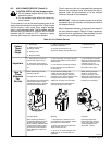
BATTERY ACID can burn eyes and skin and
destroy clothing and other materials; BAT-
TERY GASES can explode and shatter bat-
tery.
• Wear a face shield, proper protective cloth-
ing, and remove all metal jewelry.
• Do not spill or splash battery fluid.
• Do not apply pressure to walls of filled bat-
tery—use battery carrier or place hands on
opposite corners when lifting battery.
• Keep sparks, flames, cigarettes, and other ig-
nition sources away from batteries.
• Use enough ventilation to keep battery gases
from building up during and for several hours
after battery charging.
• Do not touch or move connections on battery
while battery charger is on.
• Turn battery charger off before making con-
nections to battery.
• Do not lean over battery when charging.
• Be sure battery charger connections to bat-
tery are clean and tight.
• Keep vent caps in place and cover top of bat-
tery with damp cloth.
• Be sure battery charger output matches bat-
tery voltage.
• Turn the battery charger off before discon-
necting the charger from the battery.
1. Remove battery from unit, and place on a level
worktable or other suitable surface.
2. If battery has removable vent caps, check the
condition of the electrolyte as follows:
a. Check electrolyte temperature in one of the
center cells with a battery thermometer. For
each 10°F (6°C) increment above 80°F (27°C),
a correction factor of 0.004 specific gravity
must be added to the specific gravity reading
taken in Step 2b. For each 10°F (6°C) incre-
ment below 80°F (27°C), 0.004 must be sub-
tracted from the reading taken in Step 2b.
b. Check the specific gravity of each cell with a hy-
drometer. (Draw in and expel the electrolyte two
or three times from the first cell to be tested to
adjust the temperature of the hydrometer to
that of the electrolyte.)
c. If a corrected specific gravity reading of 1.225 at
80°F (27°C) is not obtained, replace the vent
caps and recharge the battery following the bat-
tery charger manufacturer’s instructions.
3. If the battery does not have removable vent caps,
check the condition of the battery as follows:
a. Check the stabilized open−circuit voltage of the
battery. For a 12 volt battery, any reading below
12.4 volts indicates the battery needs charging.
Disconnect both battery cables from the bat-
tery, and allow battery voltage to stabilize for
several hours.
b. If the stabilized open−circuit voltage is below
12.4 volts, charge the battery following the bat-
tery charger manufacturer’s instructions.
4. Remove damp cloth from battery.
5. Reinstall battery in unit.
6. Replace battery holddown, and tighten securely.
Do not overtighten.
7. Connect positive (+) battery cable to positive (+)
battery terminal.
8. Connect negative (−) battery cable to negative
(−) battery terminal.
8-7. GOVERNOR
The governor has been set at the factory and should not
require further adjustment.
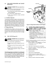
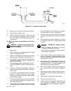
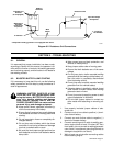
8-8. ENGINE SPEED ADJUSTMENTS (Figure 8-2)
WARNING: ELECTRIC SHOCK can kill.
• Do not touch live electrical parts.
• Stop engine, and disconnect negative (−)
battery cable from battery before inspecting,
maintaining, or servicing.
MOVING PARTS can cause serious injury.
• Keep away from moving parts such as fans,
belts, and rotors.
HOT ENGINE PARTS can cause severe
burns.
• Wear protective gloves and clothing when
working on a hot engine.
Maintenance to be performed only by qualified
persons.
The engine speeds have been factory adjusted and
should not require frequent readjustment. After tuning
the engine, check the speeds with a tachometer. With
no load applied, the weld/power speed should be 1860
rpm. If necessary, adjust the speeds as follows:
1. Open and secure right rear side door.
2. Loosen nut on end of engine speed adjusting
screw (see Figure 8-2).
3. Start the engine as instructed in Section 7-6.
4. Adjust the weld/power speed as follows:
IMPORTANT: All directions, such as clockwise and
counterclockwise, are with respect to the operator fac-
ing the rear panel of the unit.
a. To increase weld/power speed, rotate the en-
gine speed adjustment screw clockwise.
b. To decrease weld/power speed, rotate the en-
gine adjustment screw counterclockwise.