


OM-166 941 Page 16
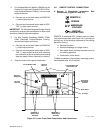
A. Auxiliary Equipment Connections To Terminal
Strip 3T (Figure 4-2)
WARNING: Read and follow safety infor-
mation at beginning of entire Section 5-2
before proceeding.
Terminal strip 3T is provided to directly wire the auxiliary
power cord(s) into the unit. To make connections, pro-
ceed as follows:
1. Remove plug from auxiliary equipment cord(s), if
applicable.
2. Open and secure lower front door.
3. Locate three strain reliefs on lower front panel.
4. Insert leads from cord(s) through a strain relief.
5. Connect leads to terminal strip 3T using terminal
information provided in Figure 4-4.
6. Secure the cord(s) in the strain relief(s).
7. Close and secure door.
B. Protection
Circuit breaker CB1 protects the 120 volts ac auxiliary
power terminals from overload. See Section 9-3 for CB1
location and resetting procedure.
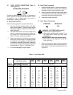
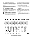
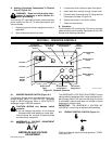
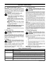
SECTION 6 − OPERATOR CONTROLS
Engine Hours
Meter
Oil Temperature
Gauge/Switch
Oil Pressure
Gauge/Switch
Battery Ampere
Gauge
Fuel Gauge
Engine Control
Switch
Check Alternator
Light
Output
(Contactor)
Switch
Ammeter
Voltmeter
Remote Amperage &
Voltage Switch
Service Engine
Air Cleaner
Light
Amperage &
Voltage Adjustment
Control
Ref. ST-147 322-E
Ampere
Ranges
Switch
Figure 8-1. Operator Controls
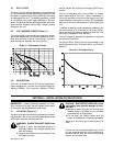
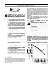
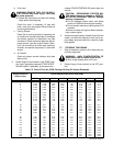
6-1. AMPERE RANGES SWITCH (Figure 6-1)
The Ampere Ranges switch provides two coarse am-
perage ranges. When in LOW OUTPUT, amperage
range is 100-350 amperes. When in HIGH OUTPUT,
amperage range is 300-800 amperes.
CAUTION: ARCING can damage switch
contacts.
• Do not change the position of the Ampere
Ranges switch while welding or under load.
Arcing causes the contacts to become pitted
and eventually inoperative.
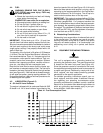
6-2. AMPERAGE & VOLTAGE ADJUSTMENT
CONTROL (Figure 6-1)
A/V
AMPERAGE AND VOLTAGE
ADJUSTMENT
The AMPERAGE & VOLTAGE ADJUSTMENT control
adjusts welding amperage within range selected by Am-
pere Ranges switch.The scale surrounding the control
is calibrated in percent and does not indicate an actual
amperage or voltage value.
IMPORTANT: The AMPERAGE & VOLTAGE AD-
JUSTMENT control may be adjusted while welding.
6-3. ENGINE CONTROL SWITCH (Figure 6-1)
The Engine Control switch has three positions: START,
RUN, and OFF.