


OM-166 941 Page 32
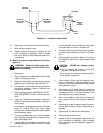
6. Start engine following procedures outlined in
Section 7 (Sequence of Operation) of this man-
ual. If the unit does not start after cranking for
twenty seconds, stop the jump starting proce-
dure. More than twenty seconds seldom starts
the engine unless some mechanical adjustment
is made.
7. Remove jumper cable from engine block.
8. Remove other end of same cable from booster
battery negative (−) terminal.
9. Remove other jumper cable from booster battery
positive (+) terminal.
10. Remove remaining end of cable from welding
generator battery positive (+) terminal.
11. Discard damp cloths.
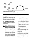
9-3. OVERLOAD PROTECTION (Figure 4-2)
WARNING: ELECTRIC SHOCK can kill.
• Do not touch live electrical parts.
• Stop engine, and disconnect negative (−) bat-
tery cable from battery before inspecting,
maintaining, or servicing.
MOVING PARTS can cause serious personal
injury.
• Keep away from moving parts such as fans,
belts, and rotors.
HOT ENGINE PARTS can cause severe
burns.
• Wear protective gloves and clothing when
working on a hot engine.
INCORRECT FUSE can damage unit.
• Be sure replacement fuse is same size, type,
and rating.
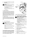
A. Circuit Breaker CB1 (Figure 4-2)
WARNING: Read and follow safety informa-
tion at beginning of Section 9-3 before pro-
ceeding.
Circuit breaker CB1 protects the 120 volts ac auxiliary
power terminals on terminal strip 3T from overload. CB1
is located behind the lower front door. When CB1 opens,
the ON/OFF switch goes to the OFF position, and 3T will
not operate. If CB1 opens, locate and correct the prob-
lem, and place the circuit breaker switch in the ON posi-
tion.
B. Circuit Breaker CB3 (Figure 4-2)
WARNING: Read and follow safety informa-
tion at beginning of Section 9-3 before pro-
ceeding.
Circuit breaker CB3 protects the unit wiring from over-
load and damage. CB3 is located behind the lower front
door.
If CB3 opens, 115 volts ac output to socket/terminal D of
REMOTE 9 receptacle RC3 and terminal strip 3T stops,
and the remote amperage/voltage control will not
function.
C. Replacement Of Low Oil Pressure/High Oil
Temperature Shutdown System Fuse F
WARNING: Read and follow safety informa-
tion at beginning of Section 9-3 before pro-
ceeding.
1. Remove securing screws, and open upper front
access door.
2. Locate shutdown switch MS1 on left, rear side of
front access door.
3. Locate fuse F on bottom of shutdown switch
MS1.
4. Remove and check fuse, and replace if neces-
sary.
5. Close and secure front access door.
9-4. CIRCUIT BOARD HANDLING PRECAU-
TIONS
WARNING: ELECTRIC SHOCK can kill
• Do not touch live electrical parts.
• Stop engine, and disconnect negative (−) bat-
tery cable from battery before inspecting,
maintaining, or servicing.
HOT ENGINE PARTS can cause severe
burns.
• Wear protective gloves and clothing when
working on a hot engine.
CAUTION: ELECTROSTATIC DISCHARGE
(ESD) can damage circuit board compo-
nents.
• Put on properly grounded wrist strap BE-
FORE handling circuit boards.
• Transport all static−sensitive components in
proper static-shielding carriers or packages.
• Perform work only at a static−safe work area.
INCORRECT INSTALLATION or misaligned
plugs can damage circuit board.
• Be sure that plugs are properly installed and
aligned before closing access door.
EXCESSIVE PRESSURE can break circuit
board.
• Use only minimal pressure and gentle move-
ment when disconnecting or connecting
board plugs and removing or installing board.
If any circuit board is not working, follow the precautions
above, and contact the nearest Factory Authorized Ser-
vice Station/Service Distributor.