


OM-166 941 Page 20
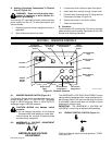
6. If remote amperage or voltage control is not
used, place AMPERAGE & VOLTAGE switch in
the PANEL position. If remote amperage or volt-
age control is to be used, place AMPERAGE &
VOLTAGE switch in the REMOTE position.
7. If remote contactor control is not used, place
OUTPUT(CONTACTOR) switch in the ON posi-
tion. If remote contactor control is to be used,
place OUTPUT(CONTACTOR) switch in the RE-
MOTE position.
8. Turn on shielding gas supply, if applicable.
9. Start engine as instructed in Section 7-6.
10. Connect desired auxiliary equipment to the 120
volts ac terminals according to Section 5.
11. Place Engine Control switch in the RUN position.
12. Energize auxiliary equipment, if applicable.
13. Wear welding helmet with proper filter lens ac-
cording to ANSI Z49.1.
14. Begin welding.
7-3. AIR CARBON ARC CUTTING AND GOUGING
(CAC-A) (Table 7-1)
WARNING: Read and follow safety informa-
tion at beginning of entire Sections 5 and 7
before proceeding.
1. Install and connect unit according to Section 4.
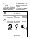
2. Wear dry insulating gloves and clothing.
3. Connect work clamp to clean, bare metal at work-
piece.
4. Place AMPERAGE & VOLTAGE switch in the
PANEL position.
5. Place OUTPUT(CONTACTOR) switch in the ON
position.
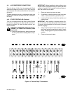
6. Set Ampere Ranges switch and rotate AMPER-
AGE & VOLTAGE ADJUSTMENT control to the
desired position (see Sections 6-1 and 6-2).
7. Start engine as instructed in Section 7-6.
8. Connect desired auxiliary equipment to the 120
volts ac terminals according to Section 5.
9. Place Engine Control switch in the RUN position.
10. Energize auxiliary equipment, if applicable.
11. Wear welding helmet with proper filter lens ac-
cording to ANSI Z49.1.
12. Begin welding.
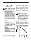
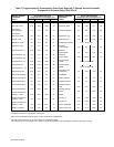
Table 7-1. Suggested Electrode Diameter For
Amperage Range (CAC-A Only)
Electrode Diameter Amperage Range
Inches Millimeters Minimum Maximum
1/8 3.2 30 60
5/32 4.0 90 150
3/16 4.8 200 250
1/4 6.4 300 400
5/16 7.9 350 450
3/8 9.5 450 600
1/2 12.7 800 1000
5/8 15.9 1000 1250
3/4 19.0 1250 1600
1 25.4 1600 2200
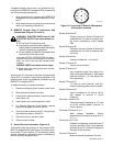
7-4. AUXILIARY POWER OPERATION
WARNING: Read and follow safety informa-
tion at beginning of entire Sections 5 and 7
before proceeding.
1. Install and connect unit according to Section 4.
2. Install and connect auxiliary power equipment
cord(s) to 120 volts auxiliary power terminals ac-
cording to Section 5-2.
3. Start engine as instructed in Section 7-6.
4. Place Engine Control switch in the RUN position.
5. Energize auxiliary equipment, if applicable. Auxil-
iary power may be obtained whenever engine is
running.
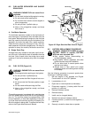
7-5. AIR COMPRESSOR OPERATION (Tables 7-2
And 7-3)
1. Install and connect unit according to Section 4.
2. Install a quick-connect connector onto the air
compressor fitting in top cover of unit.
3. Start engine as instructed in Section 7-6.
4. Begin operation.
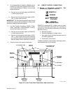
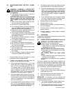
7-6. STARTING THE ENGINE
IMPORTANT: Read entire engine Owner’s Manual
(Deutz F4L-912 engine) before operating engine.
1. Engine Prestart Checks
a. Oil Level
Check engine oil level. If oil level is low, fill to top
mark on dipstick (see engine Owner’s Manual
for oil selection specifications and Section 4-5).
If oil consumption and wetstacking occur during
run-in period, see Section 8-12.