


OM-166 941 Page 33
9-5. TROUBLESHOOTING (Tables 9-1 Thru 9-4)
WARNING: ELECTRIC SHOCK can kill.
• Do not touch live electrical parts.
• Stop engine, and disconnect the negative (−)
battery cable before inspecting, maintaining,
or servicing.
MOVING PARTS can cause serious injury.
• Keep away from moving parts such as fans,
and rotors.
HOT ENGINE PARTS can cause severe
burns.
• Wear protective gloves and clothing when
working on a hot engine.
Troubleshooting to be performed only by quali-
fied persons.
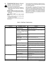
The following tables are designed to diagnose and pro-
vide remedies for some of the troubles that may develop
in this welding generator.
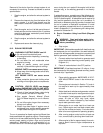
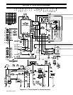
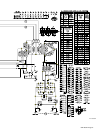
Use these tables in conjunction with the circuit diagram
while performing troubleshooting procedure. If the
trouble is not remedied after performing these proce-
dures, contact the nearest Factory Authorized Service
Station/Service Distributor. In all cases of equipment
malfunction, strictly follow the manufacturer’s proce-
dures and instructions.
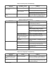
Table 9-1. Weld/Power Troubleshooting
TROUBLE PROBABLE CAUSE REMEDY
No weld output. Amperage Ranges switch S9
between positions.
Place S9 in LOW OUTPUT or HIGH OUTPUT
position (see Section 6-1).
OUTPUT (CONTACTOR)
switch S5 in REMOTE position
and Remote Contactor device
not connected.
Place S5 in ON position, or install Remote Con-
tactor Control device.
Incorrect or poor connection to
REMOTE 9 receptacle or termi-
nal strip 3T.
Check and secure connections (see Section
4-8).
Circuit breaker CB3 open
(GMAW only).
Reset CB3 (see Section 9-3).
Poor contact between slip rings
and brushes.
Clean slip rings (see Section 8-9).
Replace brushes according to Section 8-9.
Field Current Regulator board
PC1.
See Section 9-4, and contact nearest Factory
Authorized Service Station/Service Distributor.
Erratic weld output. Loose or dirty connections. Check connections both inside and outside the
unit.
Connection at work. Check connection. Be sure connection is clean
and tight.
Damp electrode. Use dry, properly stored electrode.
Field Current Regulator board
PC1.
See Section 9-4, and contact nearest Factory
Authorized Service Station/Service Distributor.
Electrode polarity. See Section 4-7C.
High welding output voltage. High engine speed. Check and adjust engine speed according to
Section 8-8.
Field Current Regulator board
PC1.
See Section 9-4, and contact nearest Factory
Authorized Service Station/Service Distributor.
Wire feeder inoperative. Circuit breaker CB3. Reset CB3 according to Section 9-3.