


OM-166 941 Page 13
If supplied remote control cord is not suitable for con-
necting to the REMOTE 9 receptacle RC3, proceed with
one of the following alternatives;
1. Wire a plug or cord to interface with REMOTE 9
receptacle RC3 using socket information in Sec-
tion C.
2. Wire remote control cord directly to terminal strip
within unit according to Section B.
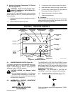
B. REMOTE Terminal Strip 3T Information And
Connections (Figures 4-2 And 4-4)
WARNING: ELECTRIC SHOCK can kill; UN-
EXPECTED OUTPUT can cause serious in-
jury.
• Do not touch live electrical parts.
• Stop engine, and disconnect negative (−)
battery cable from battery before making any
internal inspection or connections.
• Do not connect to REMOTE 9 receptacle and
terminal strip at the same time.
Since the OUTPUT (CONTACTOR) can be en-
ergized from either the receptacle or terminal
strip, it is vital to use only one remote control
method.
MOVING PARTS can cause serious injury.
• Keep away from moving parts such as fans,
belts, and rotors.
Terminal strip 3T, mounted on the lower front panel (see
Figure 4-2), is included in case the plug supplied on the
remote control cord is not suitable for connections to the
REMOTE 9 receptacle RC3.
To make connections, proceed as follows:
1. Remove existing plug from remote control cord.
2. Open and secure lower front door.
3. Locate strain reliefs provided on lower front panel
(see Figure 4-2).
4. Insert leads from cord through strain relief.
5. For Remote Electrical Cutoff Switch, remove
jumper link between terminals N and P.
6. Connect leads to terminal strip 3T using terminal
information provided in Section C.
7. Secure the cord in the strain relief.
8. Close and secure door.
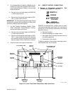
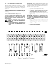
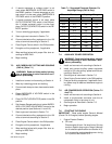
C. Socket/Terminal Information (Figure 4-4)
The following lists the functions of the sockets of RE-
MOTE 9 receptacle RC3 (see Figure 4-3), and the termi-
nals of strip 3T (see Figure 4-4). The following socket/
terminal information is provided in case it is necessary to
wire the auxiliary equipment cord.
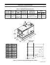
A
B
C
D
E
F
G
H
I
Ref. S-0706
Figure 4-3. Front View Of Remote 9 Receptacle
With Socket Locations
Socket A/Terminal A:
Contact closure to Socket B/Terminal B
completes the 115 volts ac contactor con-
trol circuit; protected by circuit breaker
CB3.
Socket B/Terminal B:
Contactor closure to Socket A/Terminal A
completes the 115 volts ac contactor con-
trol circuit.
Socket H/Terminal J:
Command reference; +10 volts dc.
Socket F/Terminal G:
Control circuit common.
Socket G/Terminal H:
Input command signal from wiper of re-
mote control potentiometer; 0 volts equals
machine minimum; +10 volts equals ma-
chine maximum.
Socket C/Terminal C:
115 volts ac circuit common; also con-
nected to welding power source chassis.
Socket D/Terminal D:
Up to 10 amperes of 115 volts ac, 60 Hz,
with respect to terminal C (circuit
common).
Terminals L and M of 3T:
Terminals supply 30 amperes of 115 volts
ac, 60 Hz, auxiliary power. Terminal L is
circuit common.
Terminals E/Terminal E or F:
Weld Voltage Feedback. Polarity
determined by connection at terminal E (+)
or F (−).
Terminal N and P of 3T:
Closed circuit between terminals N and P
is normal condition. Open circuit between
terminals N and P is Remote Emergency
Electrical Cutoff condition.
Terminal I/Terminal K:
Machine chassis (Equipment Ground).