


OM-166 941 Page 30
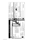
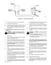
+−
+−
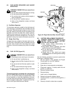
Welding
Generator
Load Bank
Voltmeter
And
Ammeter
Weld
Cables
Negative (−)
Weld Output
Terminal
Positive (+)
Weld Output
Terminal
S-0456
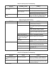
Diagram 8-1. Load Bank Connections
10. Stop engine, and disconnect load bank cables.
11. Allow exhaust system to cool.
12. Inspect inside of exhaust pipe. If pipe is dry, the
run-in procedure is complete. If pipe is coated
with a wet, black, tar-like substance, repeat run-
in procedure.
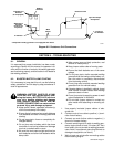
B. Run-In Procedure Using Resistance Grid (Dia-
gram 8-2)
WARNING: Read and follow safety infor-
mation at beginning of entire Section 8-12
before proceeding.
1. Stop engine.
2. Obtain resistance grid adequately sized for rated
output of welding generator.
3. Obtain two weld cables of proper size to connect
resistance grid to generator (see Section 4-7).
4. If a voltmeter and ammeter are not provided on
the welding generator, obtain a voltmeter and
clamp-on dc ammeter.
5. Place welding generator AMPERAGE & VOLT-
AGE ADJUSTMENT control in the minimum po-
sition.
6. Adjust grid switches and generator controls to
provide a load approximately equal to rated gen-
erator output.
For example, if rated generator output is 350 am-
peres, 40 volts at 100% duty cycle, adjust
switches until values indicated by meters equals
rated generator output.
7. Connect one weld cable to grid input receptacle
and remaining weld cable to grid output recep-
tacle (see Diagram 8-2).
8. If a voltmeter and ammeter are provided on the
welding generator, proceed to Step 9. If meters
are not provided, connect voltmeter and clamp-
on dc ammeter as shown in Diagram 8-2.
9. Connect remaining ends of weld cables to gener-
ator weld output terminals (polarity is not impor-
tant).
10. Start engine as instructed in Section 7-6, and al-
low engine to warm up for approximately three
minutes.
CAUTION: ARCING can damage switch
contacts.
• Do not change the position of the grid
switches while engine is running.
Arcing causes the contacts to become pitted
and eventually inoperative.
11. Check meters. Adjust load with generator con-
trols or, if necessary, by changing positions of grid
switches until values indicated by meters equal
rated generator output.
12. Allow engine to run under load for at least one
hour. Check engine and meters after the first five
minutes and every 15 minutes thereafter to be
sure equipment is operating properly
13. After running engine under load for at least one
hour, remove load by shutting down resistance
grid.
14. Allow engine to idle for approximately three min-
utes to permit internal engine temperatures to
equalize.
15. Stop engine, and disconnect weld cables.
16. Allow exhaust system to cool.
17. Inspect inside of exhaust pipe. If pipe is dry, the
run-in procedure is complete. If pipe is coated
with a wet, black, tar-like substance, repeat run-
in procedure.