


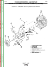

ENGINE/ROTOR REMOVAL AND
REPLACEMENT (KIT S20788) (continued)
REASSEMBLY PROCEDURE
NOTE: Lincoln Electric recommends that a new
bearing (Lincoln part #M9300-85) be installed
when you replace the rotor and blower assembly.
1. Clean the tapered engine crankshaft. Slide
the rotor onto the shaft.
2. Insert the rotor thru-bolt, and with the torque
wrench tighten the bolt to 50 ft lbs.
3. Support the engine/rotor assembly with the
chain hoist. Fit the rotor into the stator frame,
being careful not to damage the rotor core
against the stator. The bearing will seat into
its race about half way.
4. Insert the four bolts and lock washers that hold
the engine to the stator. With the 9/16”
wrench, draw the bolts up evenly in order to
seat the bearing properly. Tighten to 22 ft-lb.
moving diagonally from bolt to bolt.
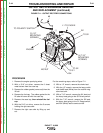
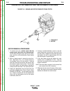
5. Check the rotor-stator air gap with the .017
feeler gauge. The measurement is taken at
the blower end of the rotor before the fan is
reinstalled. Turn the rotor with a pair of lock-
ing pliers as necessary so that the rotor “iron”
is up to take the measurement. (The rotor has
two flat sides, which are not measured for air
gap.) Slide in the gauge. Then rotate the
shaft 180 degrees and measure again. If the
gauge does not clear, loosen the four
engine/stator bolts; retighten the bolts and
recheck the air gap. Repeat until the proper
.017 minimum air gap is achieved.
6. Fasten the ground lead to the right engine
mounting bolt and install both bolts.
7. Install the brush holder bracket back into the
stator frame. Refer to the topic “Brush
Removal and Replacement” in this section of
the manual.
8. Attach leads to the oil pressure switch refer to
wiring diagram. Replace any cut cable ties.
9. Unplug the fuel tank connection and fuel hose
and connect them.
10. Connect the idle linkage to the idler rod. Snap
the plastic clip back into place.
11. Connect the engine choke cable at the posi-
tion marked during disassembly.
12. Screw the blower fan back onto the end of the
rotor shaft. Be sure the washer is in place and
hand tighten the fan only.
13. Reposition the vertical fan baffle and secure it
with the two screws.
14. Install the two cowling covers at the rear of the
stator.
15. Connect the black plug in front of the fuel tank
fill spout.
16. Connect the leads to the starter solenoid and
replace any cable ties cut during disassembly.
17. Install the battery. Connect the positive bat-
tery cable, then the negative battery cable. BE
SURE TO CONNECT THE POSITIVE BAT-
TERY CABLE FIRST.
18. Replace the battery cover.
19. Reinstall the case side, fuel cap, lift bail gas-
ket, and case top. Connect the spark plug
wires.
20. Conduct the “Retest after Repair” procedure,
the following topic in this section of the manu-
al.
TROUBLESHOOTING AND REPAIR
F-51 F-51
EAGLE™ 10,000
Return to Section TOC Return to Section TOC Return to Section TOC Return to Section TOC
Return to Master TOC Return to Master TOC Return to Master TOC Return to Master TOC