


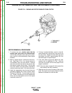

OUTPUT RECTIFIER BRIDGE REMOVAL
AND REPLACEMENT (continued)
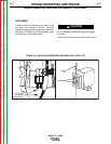
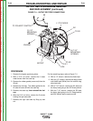
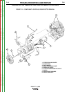
12. With the 1/2” wrench remove the three mount-
ing nuts. Note the placement of the nylon
insulators.
13. Remove the rectifier assembly by tilting it up
and lifting it toward the side of the machine.
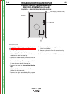
14. Reassembly: Refer to the Wiring Diagram for
proper connections to the positive and nega-
tive sides of the rectifier assembly. The two
sides of the bridge are marked + and -,
respectively.
NOTE: Use Dow Corning 340 on all aluminum
electrical connection surfaces.
15. With the 1/2” wrench install the three mounting
nuts.
16. With a 7/16” socket wrench, install the S2 lead
and the heavy lead going to the S1 Range
switch. Note the order of fasteners: flat wash-
er at the bottom followed by pigtails, heavy
leads, flat washer, lock washer, and nut.
17. With the 7/16” socket wrench, install the W1
lead and the heavy lead going to the S2
Polarity switch. Note the order of fasteners:
flat washer at the bottom followed by pigtails,
heavy leads, flat washer, lock washer, and nut.
18. With a 1/2” socket wrench, install the heavy
cable and the #8 lead (White) to the rectifier
negative heat sink. Note the order of fasten-
ers.
19. With the 1/2” socket wrench, install the choke
lead and the #10 lead and note the order of
fasteners.
20. Reinstall the case side, fuel cap, lift bail gas-
ket, case top, and spark plug wire.
TROUBLESHOOTING AND REPAIR
F-45 F-45
EAGLE™ 10,000
Return to Section TOC Return to Section TOC Return to Section TOC Return to Section TOC
Return to Master TOC Return to Master TOC Return to Master TOC Return to Master TOC