


BRUSH REMOVAL AND REPLACEMENT (continued)
PROCEDURE
1. Remove the spark plug wires.
2. With a 5/16” nut driver, remove the 6 sheet
metal screws from the case top.
3. Remove the rubber gasket (cover seal) from
the lift bail.
4. Remove the fuel cap. The rubber gasket for
the fill tube with come off with the case top.
5. Remove the case top, then reinstall the fuel
cap.
6. WIth the 5/16” nut driver, remove the 5 screws
holding the right case side.
7. Remove the right case side by lifting up and
out.
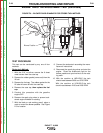
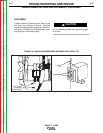
8. With a needle nose pliers, gently remove the
blue and the red wires from the brushes. See
Figure F.9.
9. With a 7/16” wrench, remove the brush holder
assembly bracket from the stator frame.
10. With a 5/16” open end wrench, remove the two
screws that secure the brush holder assembly
to the bracket. Slide the brush holder assem-
bly out of the bracket.
11. To change the brushes, use a slot head screw
driver to pop off the plastic retainer on the back
of the brush holder assembly.
12. Remove the old brushes and insert the new
ones. One corner of the terminal clip is
beveled so that the brush can go in only one
way.
13. Snap the plastic retainer back onto the brush
holder. The brushes may need some reposi-
tioning; wiggle them slightly to help them seat
properly on the slip rings.
14. To reinstall the brushes, depress the spring-
loaded brushes into the holder and slip a suit-
able non-metallic, fairly stiff retainer through
the slots at the top and bottom of the holder. A
cable tie works well; See Figure F.9. This will
hold the brushes up so that you can easily
install the holder.
15. Slide the brush holder assembly back into the
bracket and, with the 5/16” open end wrench,
install the two screws that hold it in place.
16. With the 7/16” wrench, install the brush holder
assembly bracket to the stator frame.
17. Slowly remove the non-metallic retainer from
the brush holder and let the brushes snap
back against the slip rings.
18. With the needle nose pliers, connect the red
and the black wires to the appropriate termi-
nals on the brushes. The red wire is inboard.
19. Check the wire connections for clearance and
tightness.
20. Reinstall the case side, fuel cap, lift bail gas-
ket, case top, and spark plug wires.
TROUBLESHOOTING AND REPAIR
F-36 F-36
EAGLE™ 10,000
Return to Section TOC Return to Section TOC Return to Section TOC Return to Section TOC
Return to Master TOC Return to Master TOC Return to Master TOC Return to Master TOC